


Inductance resistance type current limiter
Environmental usage conditions:
a. The altitude of the area of use shall not exceed 1000m.
b. The ambient temperature in the area of use: -40~+45 ℃.
c. The place of use should be free from severe mechanical vibration, harmful gases and vapors, and conductive or explosive dust.
4.2 Other usage conditions:
Before the capacitor is put into operation, the remaining voltage between its terminals should not exceed 10% of the rated voltage. When capacitors involve high relative humidity, rapid mold growth, corrosive atmosphere, pollution, and altitude exceeding 1000m
Keywords:
Inductance resistance type current limiter
Details
1. Use
GZX series inductance resistance type current limiter (hereinafter referred to as the current limiter) is connected in series with shunt capacitor bank, as a supporting equipment to limit the closing inrush current of shunt capacitor bank and eliminate the influence of capacitor discharge current increase when the power system short circuit.
2. Principle and function
1. Working principle of current limiting reactor
The current limiting reactor (hereinafter referred to as the current limiting reactor) is composed of CKDK type dry hollow series reactor with low inductance (hereinafter referred to as the reactor) and QR type damping resistor with graphite electrode (hereinafter referred to as the damper). Its working principle is to make comprehensive use of the reactor to present high impedance to the high frequency inrush current when shunt capacitor banks are put into the grid to limit the amplitude of inrush current and the damping resistance consumes the oscillation energy to accelerate the inrush current attenuation. Graphite electrodes are added to make use of the spark gap so that the damping resistance is only connected to the circuit at the moment when the capacitor bank is put into the grid. With the rapid attenuation of the inrush current, the voltage at both ends of the reactor drops, the graphite gap automatically extinguishes arc, and the damping resistance is scattered out, so as to avoid the power consumption caused by the long-term access of the damping resistance. So the current limiter and the series reactor usually used in the working principle and composition of a significant difference.
2. Current limiting reactor function
2.1 Good current limiting effect can be obtained.
2.2 It can eliminate the influence of discharge current of large capacity shunt capacitor device on the system short-circuit current.
2.3 The overvoltage level and the probability of multiple rebreakdowns can be reduced.
3. Model and classification
1. Model meaning:
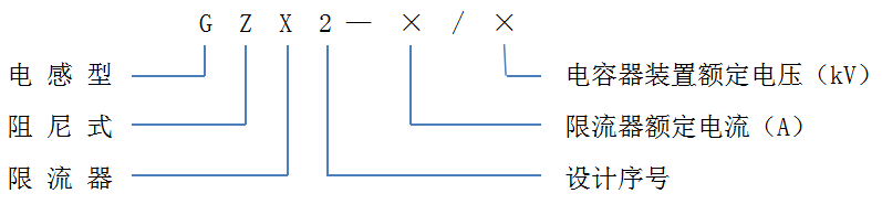
2. Product classification
2.1 The voltage level of the product is divided into 6kV and 10kV.
2.2 The main products of 6kV class have four kinds of rated current: 100A, 200A, 400A and 600A.
2.3 The main products of 10kV and 35kV class have four kinds of rated current: 160A, 250A, 400A and 600A.
2.4 The main products of 10kV and 35kV class have four kinds of rated current: 160A, 250A, 400A and 600A.
2. 5 Special specifications of 6kV, 10kV, 35kV class current limiter can be customized.
4. Structural characteristics
1. Inductance resistance type current limiting reactor is composed of two parts: reactor and damper.
2. The reactor is of dry hollow structure. The coil is wound with high quality bare copper wire or aluminum wire, and the turns are padded with glass fiber block. The whole coil is fastened with non-magnetic clamp, which can meet the requirements of mechanical strength and dynamic thermal stability. The product allows long-term operation at 1.3 times the rated current, and has the advantages of low energy consumption, low investment and easy maintenance.
3. The damper resistor is air - cooled and assembled by plate - shaped resistance element. The damping resistor is placed inside the reactor coil. It has compact structure and good electrical performance and mechanical strength.
4. Graphite electrode adjustment is flexible, two ball pole axis center (that is, the concentricity) is not more than 2mm.
5. Main technical performance
1. Rated parameter
Table 1. Rated parameters of 6kV series current limiter
| Rated inductance (μH) |
100 |
|||
| Rated inductive reactance (Ω) |
0.0314 |
|||
| Rated current (A) |
100 |
200 |
400 |
600 |
| Damper resistance (Ω) |
1.46 |
0.93 |
0.64 |
0.47 |
| Long-term allowable current of damper (A) |
2.4 |
7.7 |
23.4 |
68.4 |
Table 2. Rated parameters of 10kV series current limiter
| Rated inductance (μH) |
200 |
|||
| Rated inductive reactance (Ω) |
0.0628 |
|||
| Rated current (A) |
160 |
250 |
400 |
600 |
| Damper resistance (Ω) |
2.1 |
1.6 |
1.3 |
1.0 |
| Long-term allowable current of damper (A) |
3.7 |
10.7 |
23.1 |
42.9 |
Table 3. Rated parameters of 35kV series current limiter
| Rated inductance (μH) |
800 |
|||
| Rated inductive reactance (Ω) |
0.2512 |
|||
| Rated current (A) |
160 |
250 |
400 |
600 |
| Damper resistance (Ω) |
6.4 |
5.0 |
3.9 |
3.1 |
| Long-term allowable current of damper (A) |
6.8 |
14.4 |
31.1 |
63.4 |
2. Thermal stability
The reactor can withstand 25 times the rated current (power frequency), continuous 2s, conductive part of the temperature does not exceed 250℃, and does not produce any thermal and mechanical damage.
3. Dynamic stability
3.1 Reactor can withstand 2.5×25 times rated current (power frequency), duration of 0.2s, without electrical flashover, breakdown and mechanical damage.
3.2 Reactors and dampers are allowed to flow through high frequency attenuated discharge currents of 15kA (peak) and 10kA (peak), respectively, without electrical flashover, breakdown and mechanical damage.
4. overcurrent
Under the action of fundamental wave and harmonic current, the current limiter can run continuously when the effective value of the synthesized current does not exceed 1.3 times the rated current.
5. Temperature rise
When the reactor is tested for temperature rise, its temperature rise shall not exceed the temperature rise limit 70K, and the maximum hot spot temperature shall not exceed 130℃ (Grade B insulation).
6. Insulation level
The insulation level of the current limiter installed on the insulated bench conforms to the requirements in Table 4. Table 4
| System rated voltage (effective value) kV | Power frequency withstand voltage (dry, wet test) 1min kV | Impulse withstand voltage (peak) 1.2/50μs kV |
|
6 |
32 |
60 |
|
10 |
42 |
75 |
|
35 |
95 |
200 |
Installation, use and acceptance
1. See Figure 1 for the principle connection between the current limiter and the shunt capacitor bank.
2. See Figure 2 for the outline diagram of the 6kV and 10kV current limiter.
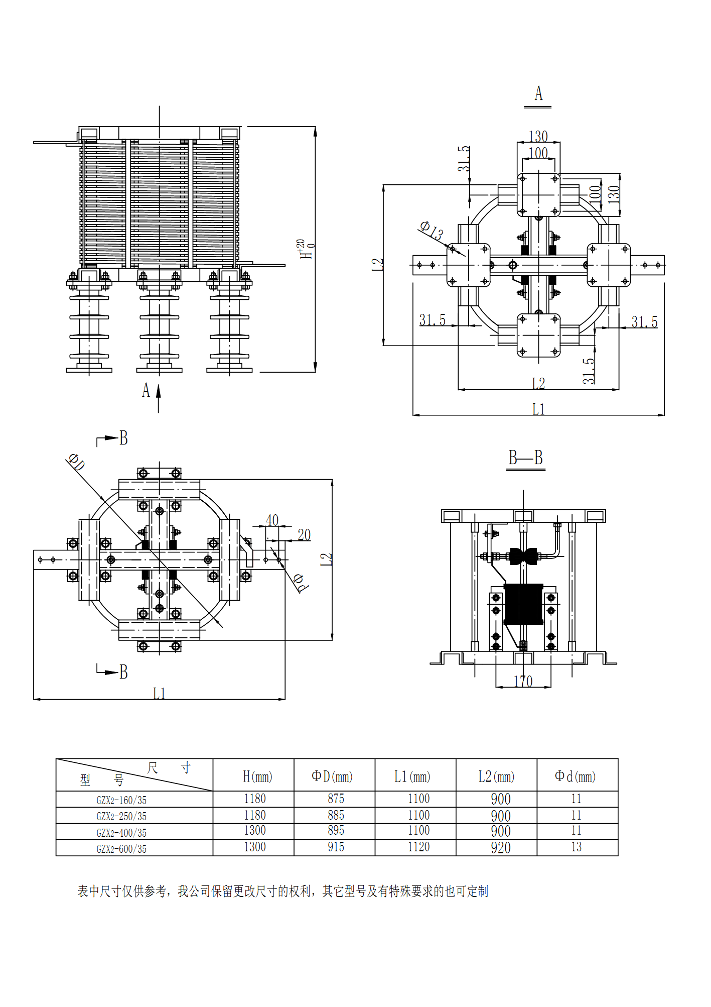
3. See Figure 3 for the schematic diagram of the dimensions of 35kV current limiter
4. The current limiter should be installed on an insulated platform, and its insulation level to the ground should be consistent with that of the voltage level of the connected power grid. If the current limiter is connected in series to the power side of the capacitor bank, it shall be installed separately. If the current limiter is connected in series to the neutral side of the capacitor bank, it can be installed separately or on the same insulated platform.
5. Setting of spark gap: The breakdown voltage setting value of spark gap is 1800 ~ 2500V (gap distance is about 1 ~ 2.0mm), and the operating voltage is based on the average value of three times.
6. Installation and service conditions
6.1 Installation Environment: Indoor.
6.2 Ambient Temperature: -40 ° C to +45 ° C
6.3 Altitude: ≤1000m.
6.4 Relative humidity: Daily average relative humidity ≤95%, monthly average relative humidity ≤90%.
6.5 Maximum Wind speed: 35m/s.
6.6 Seismic requirements: The maximum intensity of the earthquake is 8 degrees.
6.7 Installation location: There should be no harmful gas, vapor, electrical conductivity or explosive dust.
7. The matching specifications of current limiter and shunt capacitor bank are shown in Table 5, Table 6 and Table 7.
Table 5 Selection of current limiter specifications for parallel capacitor devices of 6kV(with phase voltage 6.6/√3kV) class
| Shunt capacitor device rated capacity kvar |
600 |
1000 |
1200 |
2000 |
2400 |
4200 |
5000 |
6000 |
| Shunt capacitor rated voltage kV |
6.6/√3 |
|||||||
| Shunt capacitor rated resistance Ω |
72.6 |
43.6 |
36.3 |
21.8 |
18.2 |
10.4 |
8.7 |
7.3 |
| Capacitor unit rated current A |
52 |
88 |
105 |
175 |
210 |
367 |
437 |
525 |
| Reactance % |
0.04 |
0.07 |
0.09 |
0.14 |
0.17 |
0.30 |
0.36 |
0.43 |
| Select current limiter specifications |
GZX2-100/6 |
GZX2-200/6 |
GZX2-400/6 |
GZX2-600/6 |
||||
Table 6 Selection of current limiter specifications for shunt capacitor devices of 10kV(with phase voltage 11/√3kV) class
| Shunt capacitor device rated capacity kvar |
1000 |
2000 |
3000 |
4000 |
5000 |
7000 |
8000 |
10000 |
| Shunt capacitor rated voltage kV |
11/√3 |
|||||||
| Shunt capacitor rated resistance Ω |
122.1 |
60.5 |
40.3 |
30.3 |
24.2 |
17.3 |
15.1 |
12.1 |
| Capacitor unit rated current A |
52 |
105 |
158 |
210 |
262 |
367 |
420 |
525 |
| Reactance % |
0.051 |
0.10 |
0.16 |
0.21 |
0.26 |
0.36 |
0.42 |
0.52 |
| Select current limiter specifications |
GZX2-160/10 |
GZX2-250/10 |
GZX2-400/10 |
GZX2-600/10 |
||||
Table 7 Current limiter specification selection table for 35kV(with phase voltage 38.5/√3kV) grade shunt capacitor device
| Shunt capacitor device rated capacity kvar |
3000 |
9000 |
10000 |
15000 |
18000 |
25000 |
27000 |
40000 |
| Shunt capacitor rated voltage kV |
38.5/√3 |
|||||||
| Shunt capacitor rated resistance Ω |
494.1 |
164.5 |
148.2 |
98.8 |
82.3 |
59.3 |
54.9 |
37.1 |
| Capacitor unit rated current A |
45 |
135 |
150 |
225 |
270 |
375 |
405 |
600 |
| Reactance % |
0.05 |
0.15 |
0.17 |
0.25 |
0.31 |
0.42 |
0.46 |
0.68 |
| Select current limiter specifications |
GZX2-160/35 |
GZX2-250/35 |
GZX2-400/35 |
GZX2-600/35 |
||||
Figure 1. Wiring principle and mode of current limiter and shunt capacitor bank
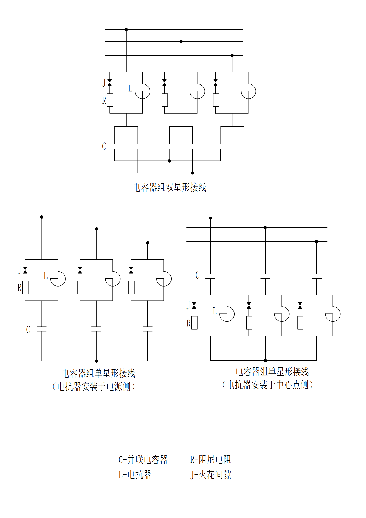
Figure 2. Schematic diagram and dimensions of 6kV and 10kV current limiter
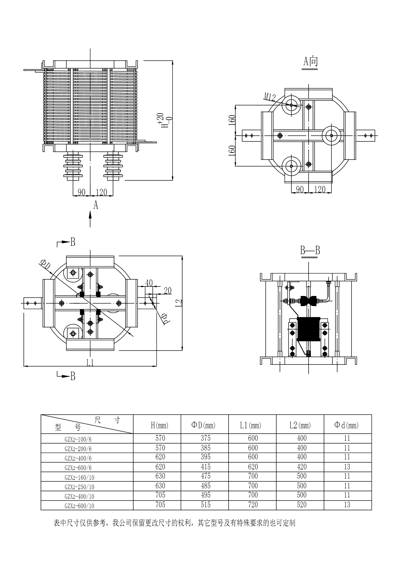
Figure 3. Schematic diagram and dimensions of 35kV current limiter
The company's product quality assurance, reliable use, GZX inductance resistance type current limiting reactor and capacitor device good compatibility, price concessions, good service. We warmly welcome users from inside and outside the province to contact us.
Online consultation
Any questions can give us a message, we have professional staff to reply to you, please be sure to fill in the correct contact information!
Recommended products

Shangyu Power Capacitor is a manufacturing company specialized in reactive power compensation and improving the power factor of the power grid.
Contact us
Address:Chengnan Industrial Function Zone, Dongguan Street, Shangyu District, Shaoxing City
E-mail:drq@sy-capacitor.com
Copyright Shaoxing Shangyu Power Capacitor Co., Ltd. Powered by:www.300.cn business license
