


Dry-type hollow series reactor
Environmental usage conditions:
a. The altitude of the area of use shall not exceed 1000m.
b. The ambient temperature in the area of use: -40~+45 ℃.
c. The place of use should be free from severe mechanical vibration, harmful gases and vapors, and conductive or explosive dust.
4.2 Other usage conditions:
Before the capacitor is put into operation, the remaining voltage between its terminals should not exceed 10% of the rated voltage. When capacitors involve high relative humidity, rapid mold growth, corrosive atmosphere, pollution, and altitude exceeding 1000m
Category:
Keywords:
Dry-type hollow series reactor
Details
I. Product use
Dry type hollow series reactor is suitable for 6, 10, 35kV power system, connected in series with shunt capacitors, used to suppress the voltage waveform distortion of the power grid, so as to change the quality of the power grid and ensure the safe operation of the power system; The harmonic current flowing through the capacitor bank is suppressed and the inrush current is limited so as to protect the capacitor for safe and reliable operation.
2. The use of environmental conditions
1. Use place: outdoor or indoor, indoor use should pay attention to ventilation and heat dissipation.
2. Ambient temperature: -40 ~ 45℃.
3. Relative humidity: monthly average is not more than 90%, daily average is not more than 95%.
4. Maximum wind speed: no more than 30m/s.
5. Altitude: No more than 1000m (above 1000m shall be stated when ordering).
6. Earthquake resistance: can withstand the intensity of 8 degrees earthquake.
7. There should be no violent vibration or turbulence in the installation and operation area.
8. The installation and operation area shall be free from harmful gas, steam, conductivity or explosive dust.
(If there is any special request, please indicate it when ordering.)
3. Implementation of standards
1. GB/T1094.6-2011 "Power transformer Part 6: reactor"
2. JB5346-2014 "Series reactor for High voltage shunt capacitors"
3. IEC280-1987 Reactor Standard
4. DL462-92 "Ordering Technical Conditions of Series reactors for High voltage Shunt capacitors"
4. Product structure
1. The reactor adopts dry hollow structure, to avoid oil leakage, inflammability and other shortcomings of oil-immersed reactor, simple maintenance, safe operation, no core, no ferromagnetic saturation, inductance value will not change with the current change, good linearity, low noise.
2. The reactor is wrapped by weft less glass ribbon impregnated with epoxy ester. The reactor coil is made of polyester film and glass wire with excellent insulation performance as the interturn insulation of the wire.
3. The reactor surface is covered with silicone organic paint resistant to ultraviolet radiation, which has good resistance to outdoor weather conditions.
4. The reactor uses polyester glass drawing rod as an axial heat dissipating airway, which has good heat dissipation performance.
5. When calculating the temperature rise of the reactor, the maximum temperature of the hot spot is taken into account, and a considerable margin is left, so as to ensure the long-term safe operation of the reactor.
6. Because the reactor adopts multi-layer parallel structure, the axial electrical stress of the coil is zero. Under the steady-state working voltage, the voltage distribution along the coil in the axial height direction is uniform.
7. Because the reactor is enclosed with weft less glass ribbon impregnated with epoxy resin, the coil has good integrity after curing, and the noise level of the reactor is below 60dB throughout its service life.
8. The reactor uses a small section of aluminum wire (Φ1.5 ~ Φ5) as the coil conductor, effectively reducing the eddy current loss in the harmonic state of the conductor.
9. Because the coil is wrapped by weft less glass ribbon impregnated with epoxy resin, the coil has a very high resistance to short circuit current due to the great mechanical force generated when the reactor passes through the short circuit current.
10. The conductive part of the reactor is welded with argon arc welding, and the mechanical structure has no fastening parts, which greatly improves the operation reliability.
11. The whole reactor structure is simple and compact, and it can run in outdoor weather conditions for a long time, without the requirement of equipment maintenance.
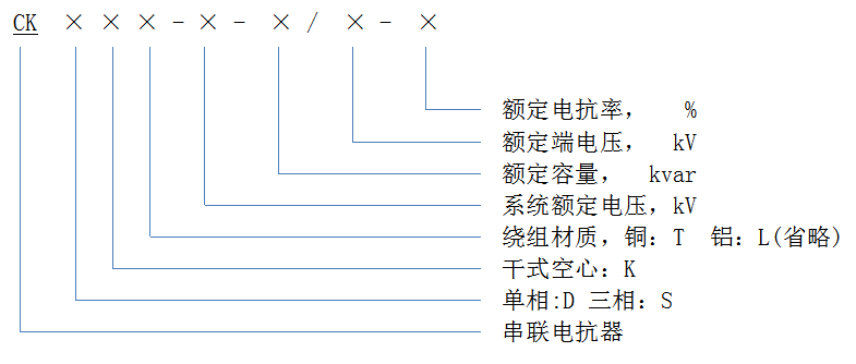
5. Main order parameters
1. Rated frequency;
2. System voltage;
3. Rated capacity of supporting capacitor bank;
4. Rated voltage of supporting capacitors;
5. Rated reactance or reactance rate of reactor;
6. Insulation level;
7. Insulation heat resistance grade;
8. Use place: indoor or outdoor;
9. Installation method and Angle between inlet and outlet lines;
10. Other special requests.
6. Model significance
7. Technical parameters and dimensions
Technical parameters of CKDK dry hollow series reactor (installation mode :1 three-phase flat or duplex flat, 2 three-phase stacked) Table 1
|
Model |
System voltage | Parallel appliance parameter | Rated capacity | Rated current | Rated reactance | reactance | Installation mode |
Outside diameter ΦD |
Install center diameter φdc |
The height to the ground is H1 | Coil height H2 | The phase distance is H3 | pivot | Coil weight | |
| Rated capacity | Rated voltage | ||||||||||||||
| kV | kvar | kV | kvar | A | Ω | % |
|
mm | mm | mm | mm | mm | Only count | kg | |
| CKDK-6-20/0.191-5 | 6 | 1200 | 6.6/√3 | 20 | 105 | 1.82 | 5 | 1 | 790 | 600 | 477 | 618 |
|
3 | 75 |
| 2 | 890 | 700 | 477 | 559 | 314 | 4 | 75 | ||||||||
| CKDK-6-24/0.229-6 | 24 | 2.19 | 6 | 1 | 690 | 500 | 477 | 765 |
|
3 | 90 | ||||
| 2 | 890 | 700 | 477 | 603 | 314 | 4 | 90 | ||||||||
| CKDK-6-48/0.499-12 | 7.2/√3 | 48 | 96.2 | 5.19 | 12 | 1 | 740 | 600 | 477 | 904 |
|
3 | 135 | ||
| 2 | 1000 | 800 | 627 | 603 | 314 | 4 | 125 | ||||||||
| CKDK-6-25/0.191-5 | 1500 | 6.6/√3 | 25 | 131.2 | 1.45 | 5 | 1 | 690 | 500 | 477 | 953 |
|
3 | 95 | |
| 2 | 870 | 700 | 477 | 717 | 314 | 4 | 85 | ||||||||
| CKDK-6-30/0.229-6 | 30 | 1.74 | 6 | 1 | 690 | 500 | 477 | 1046 |
|
3 | 105 | ||||
| 2 | 890 | 700 | 477 | 790 | 314 | 4 | 110 | ||||||||
| CKDK-6-60/0.499-12 | 7.2/√3 | 60 | 120.3 | 4.15 | 12 | 1 | 805 | 600 | 477 | 915 |
|
3 | 150 | ||
| 2 | 1105 | 900 | 627 | 737 | 314 | 4 | 155 | ||||||||
| CKDK-6-30/0.191-5 | 1800 | 6.6/√3 | 30 | 157.5 | 1.21 | 5 | 1 | 680 | 500 | 477 | 964 |
|
3 | 105 | |
| 2 | 880 | 700 | 477 | 725 | 314 | 4 | 95 | ||||||||
| CKDK-6-36/0.229-6 | 36 | 1.45 | 6 | 1 | 795 | 600 | 477 | 915 |
|
3 | 115 | ||||
| 2 | 910 | 700 | 477 | 628 | 314 | 4 | 115 | ||||||||
| CKDK-6-72/0.499-12 | 7.2/√3 | 72 | 144.3 | 3.46 | 12 | 1 | 825 | 700 | 477 | 940 |
|
3 | 170 | ||
| 2 | 1125 | 900 | 627 | 694 | 314 | 4 | 160 | ||||||||
| CKDK-6-40/0.191-5 | 2400 | 6.6/√3 | 40 | 210.0 | 0.91 | 5 | 1 | 800 | 600 | 477 | 850 |
|
3 | 115 | |
| 2 | 900 | 700 | 477 | 735 | 314 | 4 | 110 | ||||||||
| CKDK-6-48/0.229-6 | 48 | 1.09 | 6 | 1 | 800 | 600 | 477 | 941 |
|
3 | 130 | ||||
| 2 | 1000 | 800 | 627 | 755 | 314 | 4 | 125 | ||||||||
| CKDK-6-96/0.499-12 | 7.2/√3 | 96 | 192.4 | 2.59 | 12 | 1 | 935 | 800 | 477 | 902 |
|
3 | 205 | ||
| 2 | 1135 | 1000 | 627 | 694 | 314 | 4 | 190 | ||||||||
| CKDK-6-50/0.191-5 | 3000 | 6.6/√3 | 50 | 262.4 | 0.73 | 5 | 1 | 805 | 600 | 477 | 902 |
|
3 | 135 | |
| 2 | 905 | 700 | 477 | 789 | 314 | 4 | 130 | ||||||||
| CKDK-6-60/0.229-6 | 60 | 0.87 | 6 | 1 | 780 | 600 | 477 | 855 |
|
3 | 160 | ||||
| 2 | 880 | 700 | 477 | 733 | 314 | 4 | 150 | ||||||||
| CKDK-6-120/0.499-12 | 7.2/√3 | 120 | 240.6 | 2.07 | 12 | 1 | 980 | 800 | 497 | 1056 |
|
4 | 270 | ||
| 2 | 1125 | 900 | 627 | 596 | 314 | 4 | 275 | ||||||||
| CKDK-6-60/0.191-5 | 3600 | 6.6/√3 | 60 | 314.9 | 0.61 | 5 | 1 | 800 | 600 | 477 | 921 |
|
3 | 150 | |
| 2 | 960 | 800 | 627 | 642 | 314 | 4 | 145 | ||||||||
| CKDK-6-72/0.229-6 | 72 | 0.73 | 6 | 1 | 816 | 600 | 477 | 1032 |
|
3 | 170 | ||||
| 2 | 960 | 800 | 477 | 696 | 314 | 4 | 160 | ||||||||
| CKDK-6-144/0.499-12 | 7.2/√3 | 144 | 288.7 | 1.73 | 12 | 1 | 985 | 800 | 497 | 1059 |
|
3 | 275 | ||
| 2 | 1280 | 1100 | 627 | 776 | 314 | 6 | 250 | ||||||||
Table 2
| Model | System voltage | Paralleling electrical parameters | Rated capacity | Rated current | Rated reactance | Reactance rate | Installation method |
Outer diameter Φ D |
Installation pitch diameter φ dc |
Ground height H1 | Coil high H2 | Phase spacing H3 | fulcrum | Coil weight | |
| Rated capacity | Rated voltage | ||||||||||||||
| kV | kvar | kV | kvar | A | Ω | % |
|
mm | mm | mm | mm | mm | Only count | kg | |
| CKDK-6-70/0.191-5 | 6 | 4200 | 6.6/√3 | 70 | 367.4 | 0.52 | 5 | 1 | 835 | 700 | 477 | 864 |
|
3 | 170 |
| 2 | 920 | 700 | 477 | 752 | 314 | 4 | 155 | ||||||||
| CKDK-6-84/0.229-6 | 84 | 0.62 | 6 | 1 | 835 | 700 | 477 | 956 |
|
3 | 190 | ||||
| 2 | 1120 | 900 | 627 | 693 | 314 | 4 | 175 | ||||||||
| CKDK-6-168/0.499-12 | 7.2/√3 | 168 | 336.8 | 1.48 | 12 | 1 | 930 | 800 | 477 | 1310 |
|
3 | 300 | ||
| 2 | 1250 | 1100 | 627 | 768 | 314 | 6 | 280 | ||||||||
| CKDK-6-80/0.191-5 | 4800 | 6.6/√3 | 80 | 419.9 | 0.45 | 5 | 1 | 880 | 700 | 477 | 755 |
|
4 | 195 | |
| 2 | 980 | 800 | 497 | 679 | 314 | 4 | 175 | ||||||||
| CKDK-6-96/0.229-6 | 96 | 0.54 | 6 | 1 | 800 | 600 | 477 | 904 |
|
3 | 210 | ||||
| 2 | 900 | 700 | 477 | 793 | 314 | 4 | 200 | ||||||||
| CKDK-6-192/0.499-12 | 7.2/√3 | 192 | 384.9 | 1.30 | 12 | 1 | 960 | 800 | 497 | 1042 |
|
3 | 330 | ||
| 2 | 1225 | 1100 | 627 | 786 | 314 | 6 | 305 | ||||||||
| CKDK-10-16.7/0.318-5 | 10 | 1000 | 11/√3 | 16.7 | 52.5 | 6.04 | 5 | 1 | 675 | 500 | 477 | 817 |
|
3 | 85 |
| 2 | 975 | 800 | 477 | 602 | 314 | 4 | 80 | ||||||||
| CKDK-10-20/0.381-6 | 20 | 7.26 | 6 | 1 | 675 | 500 | 477 | 906 |
|
3 | 95 | ||||
| 2 | 875 | 700 | 477 | 709 | 314 | 4 | 85 | ||||||||
| CKDK-10-40/0.831-12 | 12/√3 | 40 | 48.1 | 17.28 | 12 | 1 | 780 | 600 | 477 | 1188 |
|
3 | 142 | ||
| 2 | 1080 | 900 | 627 | 830 | 314 | 4 | 135 | ||||||||
| CKDK-10-20/0.318-5 | 1200 | 11/√3 | 20 | 63.0 | 5.04 | 5 | 1 | 670 | 500 | 477 | 991 |
|
3 | 90 | |
| 2 | 1070 | 900 | 627 | 649 | 314 | 4 | 85 | ||||||||
| CKDK-10-24/0.831-6 | 24 | 6.05 | 6 | 1 | 670 | 500 | 477 | 991 |
|
3 | 100 | ||||
| 2 | 1000 | 800 | 627 | 715 | 314 | 4 | 95 | ||||||||
| CKDK-10-48/0.831-12 | 12/√3 | 48 | 57.7 | 14.40 | 12 | 1 | 785 | 600 | 477 | 1178 |
|
3 | 150 | ||
| 2 | 1185 | 1000 | 627 | 763 | 314 | 4 | 135 | ||||||||
| CKDK-10-25/0.318-5 | 1500 | 11/√3 | 25 | 78.7 | 4.03 | 5 | 1 | 675 | 500 | 477 | 1035 |
|
3 | 100 | |
| 2 | 890 | 700 | 477 | 618 | 314 | 4 | 85 | ||||||||
| CKDK-10-30/0.381-6 | 30 | 4.84 | 6 | 1 | 690 | 500 | 477 | 860 |
|
3 | 110 | ||||
| 2 | 790 | 600 | 477 | 777 | 314 | 4 | 105 | ||||||||
| CKDK-10-60/0.831-12 | 12/√3 | 60 | 72.2 | 11.52 | 12 | 1 | 790 | 600 | 477 | 1006 |
|
3 | 160 | ||
| 2 | 1190 | 1000 | 627 | 772 | 314 | 4 | 150 | ||||||||
| CKDK-10-30/0.318-5 | 1800 | 11/√3 | 30 | 94.5 | 3.36 | 5 | 1 | 675 | 500 | 477 | 1050 |
|
3 | 105 | |
| 2 | 1075 | 900 | 627 | 660 | 314 | 4 | 100 | ||||||||
| CKDK-10-36/0.381-6 | 36 | 4.03 | 6 | 1 | 690 | 500 | 477 | 1190 |
|
3 | 125 | ||||
| 2 | 985 | 800 | 497 | 686 | 314 | 4 | 115 | ||||||||
| CKDK-10-72/0.831-12 | 12/√3 | 72 | 86.6 | 9.60 | 12 | 1 | 905 | 700 | 427 | 1030 |
|
3 | 170 | ||
| 2 | 1195 | 1000 | 627 | 786 | 314 | 4 | 160 | ||||||||
Table 3
| Model | system voltage | Parallel appliance parameter | Rated capacity | Rated current | Rated reactance | Reactance rate | Installation method | Outer diameter Φ D | Installation pitch diameter φ dc | Ground height H1 | Coil high H2 | Phase spacing H3 | fulcrum | Coil weight | |
| Rated capacity | Rated voltage | ||||||||||||||
| kV | kvar | kV | kvar | A | Ω | % |
|
mm | mm | mm | mm | mm | Only count | kg | |
| CKDK-10-33.4/0.318-5 | 10 | 2000 | 11/√3 | 33.4 | 105.0 | 3.02 | 5 | 1 | 700 | 500 | 477 | 839 |
|
3 | 115 |
| 2 | 900 | 700 | 477 | 648 | 314 | 4 | 110 | ||||||||
| CKDK-10-40/0.381-6 | 40 | 3.63 | 6 | 1 | 700 | 500 | 477 | 897 |
|
3 | 125 | ||||
| 2 | 1000 | 800 | 627 | 644 | 314 | 4 | 120 | ||||||||
| CKDK-10-80/0.831-12 | 12/√3 | 80 | 96.2 | 8.64 | 12 | 1 | 845 | 700 | 477 | 10690 |
|
3 | 220 | ||
| 2 | 1225 | 1000 | 627 | 720 | 314 | 6 | 205 | ||||||||
| CKDK-10-40/0.318-5 | 2400 | 11/√3 | 40 | 126.0 | 2.52 | 5 | 1 | 775 | 600 | 477 | 721 |
|
3 | 125 | |
| 2 | 855 | 700 | 477 | 640 | 314 | 4 | 125 | ||||||||
| CKDK-10-48/0.381-6 | 48 | 3.02 | 6 | 1 | 780 | 600 | 477 | 798 |
|
3 | 140 | ||||
| 2 | 955 | 800 | 497 | 635 | 314 | 4 | 135 | ||||||||
| CKDK-10-96/0.831-12 | 12/√3 | 96 | 115.5 | 7.20 | 12 | 1 | 855 | 700 | 477 | 1062 |
|
3 | 240 | ||
| 2 | 1175 | 1000 | 627 | 741 | 314 | 4 | 210 | ||||||||
| CKDK-10-45/0.318-5 | 2700 | 11/√3 | 45 | 141.7 | 2.24 | 5 | 1 | 760 | 600 | 477 | 714 |
|
3 | 135 | |
| 2 | 1060 | 900 | 627 | 553 | 314 | 4 | 135 | ||||||||
| CKDK-10-54/0.381-6 | 54 | 2.67 | 6 | 1 | 760 | 600 | 477 | 783 |
|
3 | 150 | ||||
| 2 | 940 | 800 | 477 | 644 | 314 | 4 | 140 | ||||||||
| CKDK-10-108/0.831-12 | 12/√3 | 108 | 129.9 | 6.40 | 12 | 1 | 960 | 800 | 497 | 952 |
|
3 | 230 | ||
| 2 | 1155 | 1000 | 627 | 773 | 314 | 4 | 215 | ||||||||
| CKDK-10-50/0.318-5 | 3000 | 11/√3 | 50 | 157.5 | 2.02 | 5 | 1 | 765 | 600 | 477 | 750 |
|
3 | 150 | |
| 2 | 950 | 800 | 497 | 591 | 314 | 4 | 145 | ||||||||
| CKDK-10-60/0.381-6 | 60 | 2.42 | 6 | 1 | 790 | 600 | 477 | 790 |
|
3 | 160 | ||||
| 2 | 1110 | 900 | 627 | 537 | 314 | 4 | 155 | ||||||||
| CKDK-10-120/0.831-12 | 12/√3 | 120 | 144.3 | 5.75 | 12 | 1 | 845 | 700 | 477 | 1069 |
|
3 | 285 | ||
| 2 | 1010 | 800 | 627 | 839 | 314 | 4 | 260 | ||||||||
| CKDK-10-60/0.318-5 | 3600 | 11/√3 | 60 | 189.0 | 1.68 | 5 | 1 | 795 | 600 | 477 | 1077 |
|
3 | 160 | |
| 2 | 975 | 800 | 497 | 601 | 314 | 4 | 150 | ||||||||
| CKDK-10-72/0.381-6 | 72 | 2.02 | 6 | 1 | 795 | 600 | 477 | 800 |
|
3 | 180 | ||||
| 2 | 1195 | 1000 | 627 | 786 | 314 | 4 | 160 | ||||||||
| CKDK-10-144/0.831-12 | 12/√3 | 144 | 173.2 | 4.80 | 12 | 1 | 920 | 800 | 477 | 1011 |
|
3 | 310 | ||
| 2 | 1165 | 1000 | 627 | 696 | 314 | 4 | 260 | ||||||||
| CKDK-10-66.7/0.318-5 | 4000 | 11/√3 | 66.7 | 209.9 | 1.51 | 5 | 1 | 875 | 700 | 477 | 882 |
|
3 | 180 | |
| 2 | 1070 | 900 | 627 | 706 | 314 | 4 | 170 | ||||||||
| CKDK-10-80/0.381-6 | 80 | 1.81 | 6 | 1 | 830 | 600 | 477 | 742 |
|
3 | 200 | ||||
| 2 | 1145 | 1000 | 627 | 725 | 314 | 4 | 180 | ||||||||
| CKDK-10-160/0.831-12 | 12/√3 | 160 | 192.5 | 4.32 | 12 | 1 | 860 | 700 | 477 | 1111 |
|
3 | 335 | ||
| 2 | 1170 | 1000 | 627 | 739 | 314 | 4 | 315 | ||||||||
Table 4
| Model | System voltage | Paralleling electrical parameters | Rated capacity | Rated current | Rated reactance | Reactance rate | Installation method |
Outer diameter Φ D |
Installation pitch diameter φ dc |
Ground height H1 | Coil high H2 | Phase spacing H3 | fulcrum | Coil weight | |
| Rated capacity | Rated voltage | ||||||||||||||
| kV | kvar | kV | kvar | A | Ω | % |
|
mm | mm | mm | mm | mm | Only count | kg | |
| CKDK-10-70/0.318-5 | 10 | 4200 | 11/√3 | 70 | 220.4 | 1.44 | 5 | 1 | 870 | 700 | 477 | 866 |
|
3 | 175 |
| 2 | 1170 | 1000 | 627 | 649 | 314 | 4 | 160 | ||||||||
| CKDK-10-84/0.381-6 | 84 | 1.73 | 6 | 1 | 875 | 700 | 477 | 982 |
|
3 | 210 | ||||
| 2 | 1170 | 1000 | 627 | 730 | 314 | 4 | 190 | ||||||||
| CKDK-10-168/0.831-12 | 12/√3 | 168 | 202.1 | 4.11 | 12 | 1 | 965 | 800 | 497 | 963 |
|
3 | 315 | ||
| 2 | 1160 | 1000 | 627 | 763 | 314 | 4 | 285 | ||||||||
| CKDK-10-75/0.318-5 | 4500 | 11/√3 | 75 | 236.2 | 1.34 | 5 | 1 | 875 | 700 | 477 | 885 |
|
3 | 190 | |
| 2 | 1150 | 1000 | 627 | 692 | 314 | 4 | 180 | ||||||||
| CKDK-10-90/0.381-6 | 90 | 1.61 | 6 | 1 | 875 | 700 | 477 | 978 |
|
3 | 210 | ||||
| 2 | 1175 | 1000 | 627 | 745 | 314 | 4 | 200 | ||||||||
| CKDK-10-180/0.831-12 | 12/√3 | 180 | 216.5 | 3.84 | 12 | 1 | 965 | 800 | 497 | 986 |
|
3 | 325 | ||
| 2 | 1195 | 1000 | 627 | 759 | 314 | 4 | 300 | ||||||||
| CKDK-10-80/0.318-5 | 4800 | 11/√3 | 80 | 251.9 | 1.26 | 5 | 1 | 780 | 600 | 477 | 1062 |
|
3 | 210 | |
| 2 | 1075 | 900 | 627 | 558 | 314 | 4 | 200 | ||||||||
| CKDK-10-96/0.381-6 | 96 | 1.51 | 6 | 1 | 880 | 700 | 477 | 996 |
|
3 | 230 | ||||
| 2 | 1180 | 1000 | 627 | 748 | 314 | 4 | 220 | ||||||||
| CKDK-10-192/0.831-12 | 12/√3 | 192 | 230.9 | 3.60 | 12 | 1 | 870 | 700 | 477 | 1159 |
|
3 | 355 | ||
| 2 | 1235 | 1100 | 627 | 750 | 314 | 6 | 315 | ||||||||
| CKDK-10-83.3/0.318-5 | 5000 | 11/√3 | 83.3 | 262.4 | 1.21 | 5 | 1 | 860 | 700 | 477 | 927 |
|
3 | 210 | |
| 2 | 1205 | 1000 | 627 | 622 | 314 | 6 | 200 | ||||||||
| CKDK-10-100/0.381-6 | 100 | 1.45 | 6 | 1 | 905 | 700 | 477 | 889 |
|
3 | 230 | ||||
| 2 | 1205 | 1000 | 627 | 670 | 314 | 6 | 215 | ||||||||
| CKDK-10-200/0.831-12 | 12/√3 | 200 | 240.6 | 3.46 | 12 | 1 | 995 | 800 | 497 | 897 |
|
3 | 385 | ||
| 2 | 1395 | 1100 | 707 | 642 | 314 | 6 | 360 | ||||||||
| CKDK-10-90/0.318-5 | 5400 | 11/√3 | 90 | 283.4 | 1.12 | 5 | 1 | 910 | 700 | 477 | 820 |
|
3 | 210 | |
| 2 | 1105 | 900 | 627 | 670 | 314 | 4 | 200 | ||||||||
| CKDK-10-108/0.381-6 | 108 | 1.34 | 6 | 1 | 945 | 800 | 477 | 915 |
|
3 | 260 | ||||
| 2 | 1210 | 1000 | 627 | 681 | 314 | 6 | 240 | ||||||||
| CKDK-10-216/0.831-12 | 12/√3 | 216 | 259.8 | 3.20 | 12 | 1 | 1000 | 800 | 627 | 899 |
|
3 | 380 | ||
| 2 | 1140 | 900 | 627 | 741 | 314 | 4 | 355 | ||||||||
| CKDK-10-100/0.318-5 | 6000 | 11/√3 | 100 | 314.9 | 1.01 | 5 | 1 | 860 | 700 | 477 | 864 |
|
3 | 260 | |
| 2 | 1060 | 900 | 627 | 670 | 314 | 4 | 230 | ||||||||
| CKDK-10-120/0.381-6 | 120 | 1.21 | 6 | 1 | 960 | 800 | 497 | 797 |
|
3 | 270 | ||||
| 2 | 1160 | 1000 | 627 | 679 | 314 | 4 | 245 | ||||||||
| CKDK-10-240/0.831-12 | 12/√3 | 240 | 288.7 | 2.88 | 12 | 1 | 985 | 800 | 497 | 1459 |
|
3 | 420 | ||
| 2 | 1250 | 1100 | 627 | 694 | 314 | 6 | 360 | ||||||||
Table 5
|
Model |
system voltage | Paralleling electrical parameters | Rated capacity | Rated current | Rated reactance | Reactance rate | Installation method | Outer diameter Φ D | Installation pitch diameter φ dc | Ground height H1 | Coil high H2 | Phase spacing H3 | fulcrum |
Coil weight |
|
| Rated capacity | Rated voltage | ||||||||||||||
|
kV |
kvar |
kV |
kvar |
A |
Ω |
% |
|
mm |
mm |
mm |
mm |
mm |
Only count |
kg |
|
|
CKDK-10-110/0.318-5 |
10
|
6600 |
11/√3 |
110 |
316.4 |
0.92 |
5 |
1 |
860 |
700 |
477 |
866 |
|
3 |
260 |
|
2
|
1195 |
1000 |
627 |
618 |
314 |
4 |
235 |
||||||||
|
CKDK-10-132/0.381-6 |
132 |
1.10 |
6 |
1
|
910 |
700 |
477 |
887 |
|
3 |
280 |
||||
|
2
|
1165 |
1000 |
627 |
681 |
314 |
4 |
260 |
||||||||
|
CKDK-10-264/0.831-12 |
12/√3 |
264 |
317.5 |
2.62 |
12 |
1 |
1090 |
900 |
627 |
1282 |
|
3 |
405 |
||
|
2 |
1315 |
1100 |
707 |
665 |
314 |
6 |
375 |
||||||||
|
CKDK-10-116.7/0.318-5 |
7000
|
11/√3 |
116.7 |
367.4 |
0.86 |
5 |
1 |
865 |
700 |
477 |
890 |
|
3 |
260 |
|
|
2 |
1245 |
1000 |
627 |
596 |
314 |
6 |
235 |
||||||||
|
CKDK-10-140/0.381-6 |
140 |
1.04 |
6 |
1 |
915 |
700 |
477 |
901 |
|
3 |
285 |
||||
|
2
|
1315 |
1100 |
707 |
618 |
314 |
6 |
265 |
||||||||
|
CKDK-10-280/0.831-12 |
12/√3 |
280 |
336.8 |
2.47 |
12 |
1 |
1090 |
900 |
627 |
1307 |
|
3 |
425 |
||
|
2 |
1405 |
1200 |
707 |
763 |
314 |
6 |
410 |
||||||||
|
CKDK-10-125/0.318-5 |
7500
|
11/√3 |
125 |
393.6 |
0.81 |
5
|
1 |
920 |
700 |
477 |
822 |
|
3 |
265 |
|
|
2 |
1270 |
1100 |
707 |
707 |
314 |
6 |
250 |
||||||||
|
CKDK-10-150/0.381-6 |
150 |
0.97 |
6 |
1 |
920 |
700 |
477 |
906 |
|
3 |
295 |
||||
|
2 |
1275 |
1100 |
627 |
666 |
314 |
6 |
280 |
||||||||
|
CKDK-10-300/0.831-12 |
12/√3 |
300 |
360.8 |
2.30 |
12 |
1 |
1055 |
900 |
627 |
1251 |
|
3 |
480 |
||
|
2 |
1415 |
1200 |
727 |
740 |
314 |
6 |
435 |
||||||||
|
CKDK-10-133.4/0.318-5
|
8000
|
11/√3 |
134 |
419.9 |
0.76 |
5
|
1
|
875 |
700 |
477 |
897 |
|
3 |
300 |
|
|
2 |
1080 |
900 |
627 |
689 |
314 |
4 |
275 |
||||||||
|
CKDK-10-160/0.381-6 |
160 |
0.91 |
6 |
1 |
980 |
800 |
497 |
860 |
|
3 |
320 |
||||
|
2 |
1205 |
1000 |
627 |
682 |
314 |
6 |
290 |
||||||||
|
CKDK-10-320/0.831-12 |
12/√3 |
320 |
384.9 |
2.16 |
12 |
1 |
1060 |
900 |
627 |
1295 |
|
3 |
500 |
||
|
2 |
1415 |
1200 |
727 |
769 |
314 |
6 |
455 |
||||||||
|
CKDK-10-150/0.318-5 |
9000 |
11/√3 |
150 |
472.4 |
0.67 |
5 |
1 |
880 |
700 |
477 |
909 |
|
3 |
300 |
|
|
2 |
1130 |
1000 |
627 |
678 |
314 |
4 |
275 |
||||||||
|
CKDK-10-180/0.381-6
|
180 |
0.81 |
6
|
1 |
930 |
700 |
477 |
935 |
|
3 |
325 |
||||
|
2 |
1230 |
1100 |
627 |
683 |
314 |
6 |
305 |
||||||||
|
CKDK-10-360/0.831-12 |
12/√3 |
360 |
433.0 |
1.92 |
12 |
1 |
1120 |
900 |
627 |
909 |
|
3 |
505 |
||
|
2 |
1420 |
1200 |
727 |
789 |
314 |
6 |
465 |
||||||||
|
CKDK-10-167/0.318-5 |
10000
|
11/√3
|
167 |
524.9 |
0.60 |
5 |
1 |
900 |
700 |
477 |
894 |
|
3 |
350 |
|
|
2 |
1200 |
100 |
627 |
633 |
314 |
6 |
310 |
||||||||
|
CKDK-10-200/0.381-6 |
200 |
0.73 |
6 |
1 |
1000 |
800 |
627 |
871 |
|
3 |
365 |
||||
|
2 |
1400 |
1200 |
727 |
606 |
314 |
6 |
350 |
||||||||
|
CKDK-10-400/0.831-12 |
12/√3 |
400 |
481.1 |
1.73 |
12 |
1 |
1095 |
900 |
627 |
1180 |
|
3 |
570 |
||
|
2 |
1395 |
1200 |
727 |
835 |
314 |
6 |
520 |
||||||||
Table 6
| Model | System voltage | Paralleling electrical parameters | Rated capacity | Rated current | Rated reactance | Reactance rate | Installation method |
Outer diameter Φ D |
Installation pitch diameter φ dc |
Ground height H1 | Coil high H2 | Phase spacing H3 | fulcrum | Coil weight | |
| Rated capacity | Rated voltage | ||||||||||||||
| kV | kvar | kV | kvar | A | Ω | % |
|
mm | mm | mm | mm | mm | Only count | kg | |
| CKDK-35-66.7/1.1-5 | 35 | 4000 | 11×2 | 66.7 | 60.6 | 18.14 | 5 | 1 | 895 | 700 | 627 | 1177 |
|
3 | 180 |
| CKDK-35-80/1.32-6 | 80 | 21.78 | 6 | 1 | 995 | 800 | 627 | 1172 |
|
3 | 200 | ||||
| CKDK-35-160/2.88-12 | 12×2 | 160 | 55.6 | 51.84 | 12 | 1 | 1295 | 1100 | 727 | 1457 |
|
3 | 320 | ||
| CKDK-35-83.4/1.1-5 | 5000 | 11×2 | 83.4 | 75.8 | 14.51 | 5 | 1 | 810 | 600 | 627 | 1364 |
|
3 | 220 | |
| CKDK-35-100/1.32-6 | 100 | 17.42 | 6 | 1 | 1090 | 900 | 627 | 1137 |
|
3 | 240 | ||||
| CKDK-35-200/2.88-12 | 12×2 | 200 | 69.4 | 41.47 | 12 | 1 | 1305 | 1100 | 727 | 1315 |
|
3 | 350 | ||
| CKDK-35-100/1.1-5 | 6000 | 11×2 | 100 | 90.9 | 12.1 | 5 | 1 | 1100 | 900 | 627 | 1136 |
|
3 | 240 | |
| CKDK-35-120/1.32-6 | 120 | 14.52 | 6 | 1 | 1010 | 800 | 627 | 1247 |
|
3 | 260 | ||||
| CKDK-35-240/2.88-12 | 12×2 | 240 | 83.3 | 34.56 | 12 | 1 | 1315 | 1100 | 727 | 1383 |
|
3 | 395 | ||
| CKDK-35-116.7/1.1-5 | 7000 | 11×2 | 116.7 | 106.1 | 10.37 | 5 | 1 | 1100 | 900 | 627 | 1135 |
|
3 | 240 | |
| CKDK-35-140/1.32-6 | 140 | 12.45 | 6 | 1 | 1100 | 900 | 627 | 1269 |
|
3 | 275 | ||||
| CKDK-35-280/2.88-12 | 12×2 | 280 | 97.2 | 29.62 | 12 | 1 | 1320 | 1100 | 727 | 1408 |
|
3 | 425 | ||
| CKDK-35-133.4/1.1-5 | 8000 | 11×2 | 133.4 | 121.2 | 9.07 | 5 | 1 | 1080 | 900 | 627 | 966 |
|
3 | 290 | |
| CKDK-35-160/1.32-6 | 160 | 10.89 | 6 | 1 | 980 | 800 | 627 | 1219 |
|
3 | 320 | ||||
| CKDK-35-320/2.88-12 | 12×2 | 320 | 111.1 | 25.92 | 12 | 1 | 1375 | 1200 | 727 | 1301 |
|
3 | 475 | ||
| CKDK-35-150/1.1-5 | 9000 | 11×2 | 150 | 136.4 | 8.07 | 5 | 1 | 1080 | 900 | 627 | 969 |
|
3 | 280 | |
| CKDK-35-180/1.32-6 | 180 | 9.68 | 6 | 1 | 1180 | 1000 | 627 | 969 |
|
3 | 325 | ||||
| CKDK-35-360/2.88-12 | 12×2 | 360 | 125.0 | 23.04 | 12 | 1 | 1380 | 1200 | 727 | 1332 |
|
3 | 505 | ||
| CKDK-35-166.7/1.1-5 | 10000 | 11×2 | 166.7 | 151.5 | 7.26 | 5 | 1 | 1150 | 1000 | 627 | 887 |
|
3 | 315 | |
| CKDK-35-200/1.32-6 | 200 | 8.71 | 6 | 1 | 1145 | 1000 | 627 | 951 |
|
3 | 345 | ||||
| CKDK-35-400/2.88-12 | 12×2 | 400 | 138.9 | 20.74 | 12 | 1 | 1245 | 1100 | 627 | 1322 |
|
3 | 565 | ||
| CKDK-35-200/1.1-5 | 12000 | 11×2 | 200 | 181.8 | 6.05 | 5 | 1 | 1160 | 900 | 627 | 904 |
|
3 | 360 | |
| CKDK-35-240/1.32-6 | 240 | 7.26 | 6 | 1 | 1155 | 1000 | 627 | 1000 |
|
3 | 365 | ||||
| CKDK-35-480/2.88-12 | 12×2 | 480 | 166.7 | 17.28 | 12 | 1 | 1310 | 1100 | 727 | 1266 |
|
3 | 640 | ||
| CKDK-35-250/1.1-5 | 15000 | 11×2 | 250 | 227.3 | 4.84 | 5 | 1 | 1170 | 1000 | 627 | 920 |
|
3 | 390 | |
| CKDK-35-300/1.1-6 | 300 | 5.81 | 6 | 1 | 1170 | 1000 | 627 | 1025 |
|
3 | 445 | ||||
| CKDK-35-600/2.88-12 | 12×2 | 600 | 208.3 | 13.82 | 12 | 1 | 1465 | 1300 | 757 | 1236 |
|
6 | 685 | ||
| CKDK-35-300/1.1-5 | 18000 | 11×2 | 300 | 272.7 | 4.03 | 5 | 1 | 1145 | 1000 | 627 | 928 |
|
3 | 450 | |
| CKDK-35-360/1.32-6 | 360 | 4.84 | 6 | 1 | 1245 | 1100 | 627 | 946 |
|
3 | 500 | ||||
| CKDK-35-720/2.88-12 | 12×2 | 720 | 250 | 11.52 | 12 | 1 | 1340 | 1100 | 727 | 1372 |
|
6 | 845 | ||
| CKDK-35-333.4/1.1-5 | 20000 | 11×2 | 333.4 | 303.0 | 3.63 | 5 | 1 | 1290 | 1100 | 727 | 1310 |
|
6 | 525 | |
| CKDK-35-400/1.32-6 | 400 | 4.36 | 6 | 1 | 1290 | 1100 | 727 | 1444 |
|
6 | 555 | ||||
| CKDK-35-800/2.88-12 | 12×2 | 800 | 277.8 | 10.37 | 12 | 1 | 1350 | 1200 | 727 | 1342 |
|
6 | 860 | ||
| CKDK-35-416.7/1.1-5 | 25000 | 11×2 | 416.7 | 378.8 | 2.90 | 5 | 1 | 1300 | 1100 | 727 | 1281 |
|
6 | 540 | |
| CKDK-35-500/1.32-6 | 500 | 3.48 | 6 | 1 | 1400 | 1200 | 727 | 1323 |
|
6 | 595 | ||||
| CKDK-35-1000/2.88-12 | 12×2 | 1000 | 347.2 | 8.29 | 12 | 1 | 1675 | 1500 | 877 | 1378 |
|
6 | 1010 | ||
Table 7
| Model | System voltage | Paralleling electrical parameters | Rated capacity | Rated current | Rated reactance | Reactance rate | Installation method |
Outer diameter Φ D |
Installation pitch diameter φ dc |
Ground height H1 | Coil high H2 | Phase spacing H3 | fulcrum | Coil weight | |
| Rated capacity | Rated voltage | ||||||||||||||
| kV | kvar | kV | kvar | A | Ω | % |
|
mm | mm | mm | mm | mm | Only count | kg | |
| CKDK-35-500/1.1-5 | 35 | 30000 | 11×2 | 500 | 454.5 | 2.42 | 5 | 1 | 1370 | 1200 | 727 | 1163 |
|
6 | 610 |
| CKDK-35-600/1.32-6 | 600 | 2.90 | 6 | 1 | 1370 | 1200 | 727 | 1295 |
|
6 | 680 | ||||
| CKDK-35-1200/2.88-12 | 12×2 | 1200 | 416.7 | 6.91 | 12 | 1 | 1690 | 1500 | 877 | 1407 |
|
6 | 1130 | ||
| CKDK-35-666.7/1.1-5 | 40000 | 11×2 | 666.7 | 606.1 | 1.81 | 5 | 1 | 1415 | 1200 | 727 | 1039 |
|
6 | 730 | |
| CKDK-35-800/1.32-6 | 800 | 2.18 | 6 | 1 | 1515 | 1300 | 777 | 1062 |
|
6 | 810 | ||||
| CKDK-35-1600/2.88-12 | 12×2 | 1600 | 555.6 | 5.18 | 12 | 1 | 1710 | 1500 | 877 | 1462 |
|
8 | 1330 | ||
| CKDK-35-833.4/1.1-5 | 50000 | 11×2 | 833.4 | 757.6 | 1.45 | 5 | 1 | 1400 | 1200 | 727 | 1214 |
|
6 | 920 | |
| CKDK-35-1000/1.32-6 | 1000 | 1.74 | 6 | 1 | 1500 | 1300 | 777 | 1258 |
|
6 | 1030 | ||||
| CKDK-35-2000/2.88-12 | 12×2 | 2000 | 694.4 | 4.15 | 12 | 1 | 1805 | 1400 | 927 | 1455 |
|
8 | 1540 | ||
| CKDK-35-1000/1.1-5 | 60000 | 11×2 | 1000 | 909.1 | 1.21 | 5 | 1 | 1630 | 1400 | 827 | 1029 |
|
6 | 1065 | |
| CKDK-35-1200/1.32-6 | 1200 | 1.45 | 6 | 1 | 1630 | 1400 | 827 | 1112 |
|
6 | 1120 | ||||
| CKDK-35-2400/2.88-12 | 12×2 | 2400 | 833.3 | 3.46 | 12 | 1 | 1880 | 1600 | 977 | 1398 |
|
8 | 1790 | ||
The company's product quality assurance, reliable use, CKDK type dry hollow series reactor and capacitor device good compatibility, price concessions, good service. We warmly welcome users from inside and outside the province to contact us.
8. Hoisting, transportation and unpacking acceptance
1. This product has the packaging suitable for long-distance transportation, in the transportation, loading and unloading and hoisting occasions should avoid falling, serious collision, bumps, etc., so as to avoid product damage.
2. The product shall use the lifting ring (provided by the user), which can be lifted after mounting the lifting ring on the upper star frame and tightening the lock nut. The lifting tool is only for lifting, and must be removed before the product is put into operation to avoid local overheating.
3. Before unpacking the package, check whether the package is damaged due to fall, serious collision, violent vibration, or turbulence.
4. After unpacking the reactor, check whether the data on the reactor nameplate is complete.
5. Check whether all components are complete according to the packing list.
6. Check whether the technical documents are complete according to the packing list.
7. Check the appearance of the reactor, its components and accessories for serious defects or damage caused by serious collision.
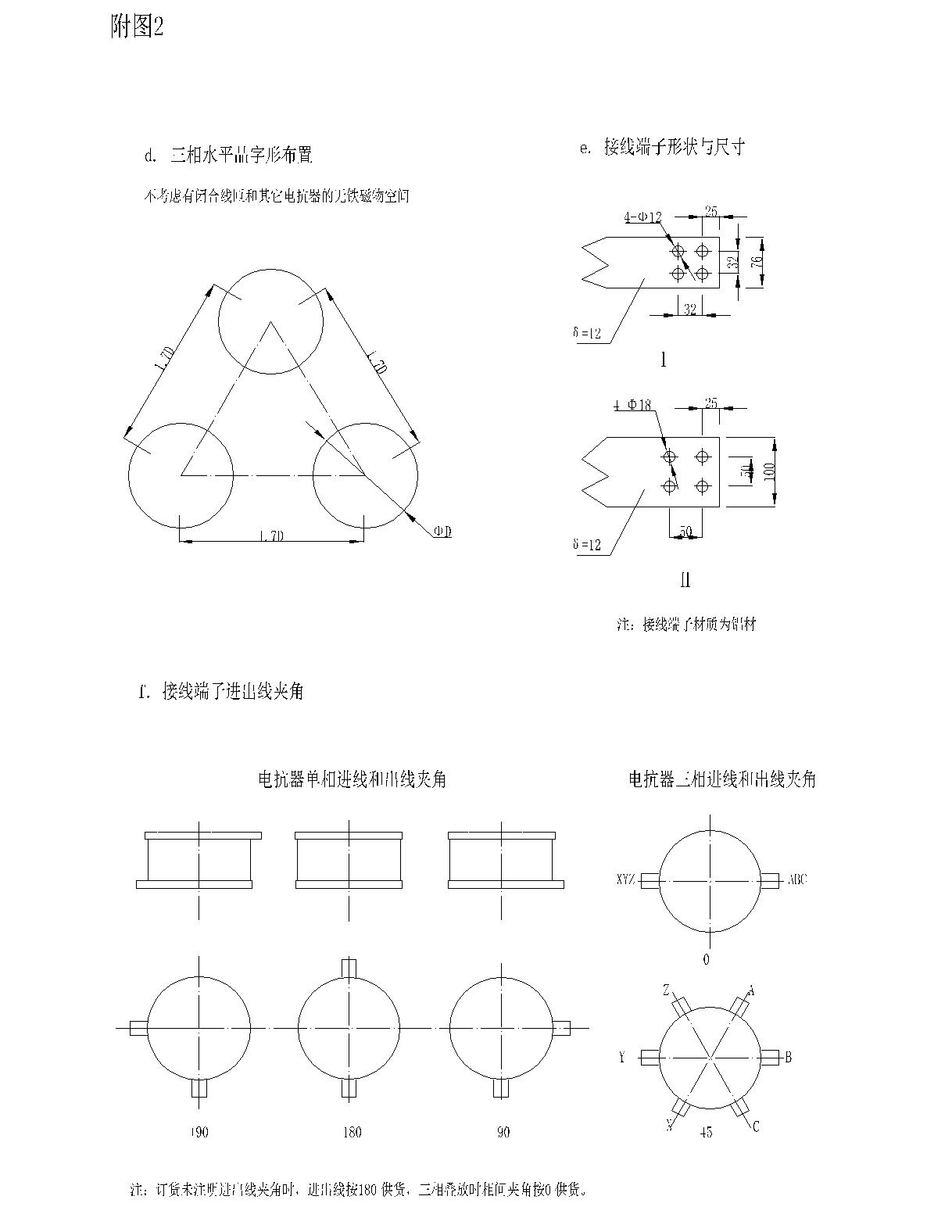
8. The exterior of the reactor is coated with outdoor anti-ultraviolet paint. The paint layer around it should be carefully checked for peeling phenomenon caused by abrasion.
9. The Buyer may, when conditions permit, carry out the following acceptance tests:
a. winding resistance measurement;
b. Power frequency voltage test, test voltage value according to the factory test value of 75% or lower voltage test.
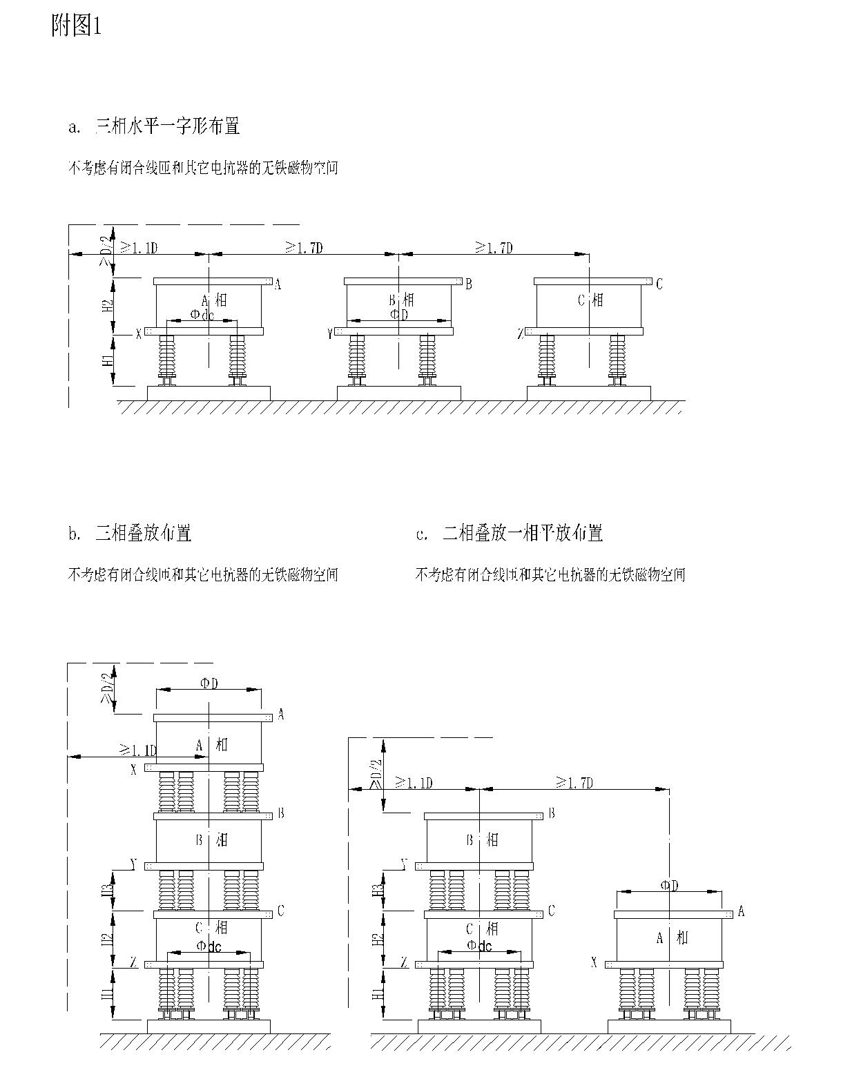
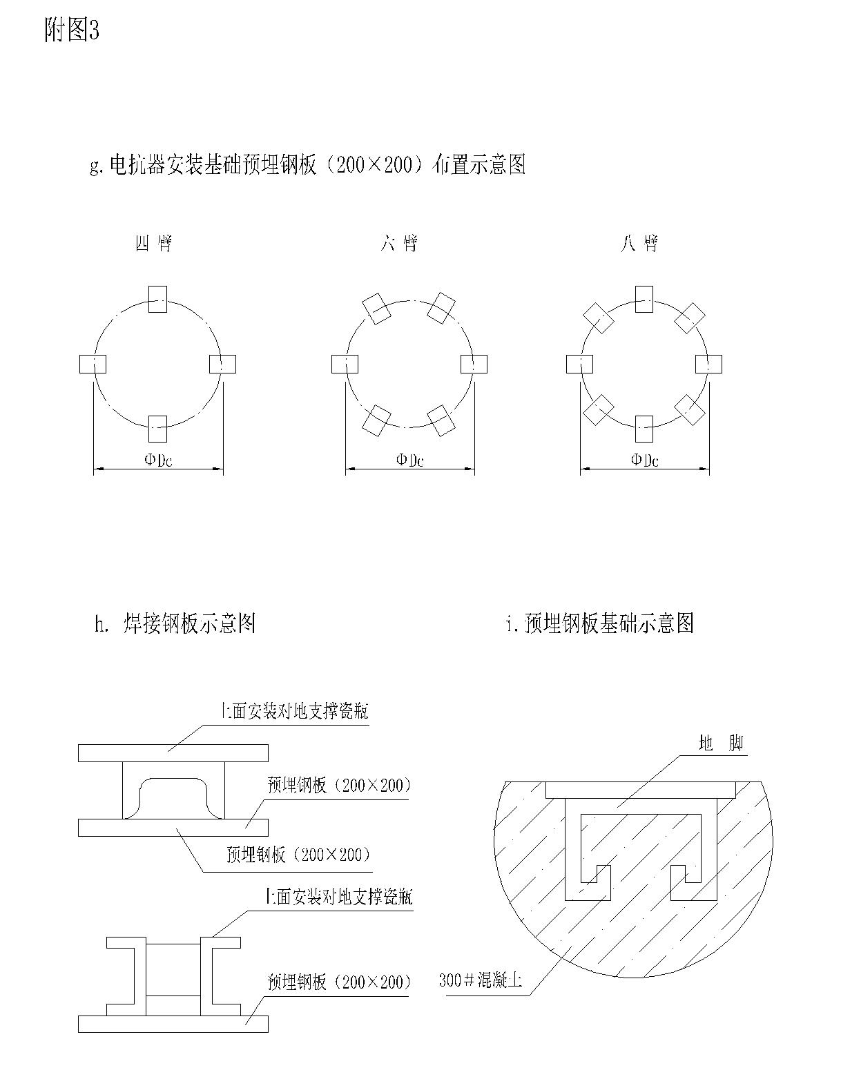
9. Installation (basic installation form and installation size are shown in the attached figure 1, 2, 3)
1. Installation site requirements
a. Both the electrical safety distance and the alternating magnetic field safety distance should be considered for the safety distance between the reactor and the metal parts around it, and the maximum value should be taken between the two. The electrical safety distance should be determined in accordance with relevant regulations.
b. There should be no coarse metal components within a distance of 1.1 times the reactor diameter from the reactor center and 0.5D from the end face of the upper and lower star frame. For large metal components and closed-loop metal components, the distance should be increased. There shall be no reinforcement and other metal members forming closed loops in the foundation under the reactor base frame.
c. When several sets of products need to be installed together, the net distance of each product shall take into account the electrical safety distance and the alternating magnetic field safety distance, and choose the greater between them. In order to avoid large influence (mutual inductance effect) between alternating magnetic fields of two products and serious change of reactor parameters, at least 1.7 times of the net distance between two reactor centers should be maintained.
d. If the reactor is installed outdoors or in a spacious workshop, there is no need for special ventilation equipment. For the reactor installed in a closed chamber, in order to ensure its heat dissipation conditions, air pumping devices should be installed in the small chamber.
2. Installation precautions
a. dry hollow reactor can be installed in two ways: stacked type and divided type, which must be installed in strict accordance with the specified installation mode, that is, the divided type of products can not be installed into stacked type or the stacked type of products can be separated by themselves to install components, so as not to change the reactor parameters and lead to failure to meet the requirements or burn the reactor. For stacked reactors, the bottom-up installation sequence should be strictly in accordance with the requirements of the installation steps, not arbitrarily reversed.
b. The reactor may vibrate or swing slightly when it is impacted by short circuit current, which is a normal phenomenon, so the reactor outlet terminal and the external connection must avoid complete steel connection, it is best to use cable under possible conditions, if it is necessary to use hard bus, the bus should also form a buffer transition bend.
c. The connecting bolts of the reactor and the supporting porcelain bottle are made of non-magnetic materials. Stainless steel bolts, nuts and washers have been provided with the product before delivery.
3. Installation steps for three-phase stacked reactors
a. Install the channel steel base under the porcelain bottle of the ground pillar with fastening bolts;
b. Install the C-phase reactor coil on the porcelain bottle of the ground pillar on the channel steel base with stainless steel screws. Add a rubber cushion in the middle and tighten it (if the gap between the coil and the porcelain bottle is too large, you can add a rubber cushion to adjust it);
c. Place the C-phase coil which has been installed with the porcelain bottle of the ground pillar on the embedded steel plate of the reactor foundation according to the installation position and the direction of the incoming and outgoing lines and weld it firmly;
d. Install the rubber pad, interphase pillar porcelain bottle, rubber pad and B-phase coil upward in turn, and tighten them (if the gap between the coil and porcelain bottle is too large, rubber pad can be added to adjust);
e. Install the rubber pad, interphase pillar porcelain bottle, rubber pad and A-phase coil upward in turn, and tighten them (if the gap between the coil and porcelain bottle is too large, add rubber pad to adjust them);
f. After the reactor coil is installed, check whether the fasteners are connected reliably and whether the positions of the inlet and outlet terminals are correct.
4. Install reactors in three-phase horizontal layout
a. Install the channel steel base under the porcelain bottle of the ground pillar with fastening bolts;
b. Install the coil of A, B and C phase reactor on the porcelain bottle of the ground pillar of the channel steel base with stainless steel screws. Add a rubber pad in the middle and tighten it (if the gap between the coil and the porcelain bottle is too large, you can add a rubber pad to adjust it);
c. According to the installation position and the direction of incoming and outlet lines, the A, B and C phase coils which have been installed with the porcelain bottles of the ground pillar are respectively placed on the embedded steel plate of their respective reactor foundation and welded securely;
f. After the reactor coil is installed, check whether the fasteners are connected reliably and whether the positions of the inlet and outlet terminals are correct.
5. Reactor installation steps of two phase stack and one phase horizontal layout
a. Install the channel steel base under the porcelain bottle of the ground pillar with fastening bolts;
b. Install the coil of A and C phase reactor on the porcelain bottle of the ground pillar of the channel steel base with stainless steel screws, and add a rubber pad in the middle and tighten it (if the gap between the coil and the porcelain bottle is too large, you can add a rubber pad to adjust it);
c. Place the A and C phase coils that have been installed with porcelain bottles of the ground pillar on the embedded steel plate of the reactor foundation according to the installation position and the direction of the inlet and outlet lines and weld them firmly;
e. Install the rubber pad, interphase pillar porcelain bottle, rubber pad and B-phase coil upward on the C-phase reactor coil, and tighten (if the gap between coil and porcelain bottle is too large, rubber pad can be added to adjust);
f. After the reactor coil is installed, check whether the fasteners are connected reliably and whether the positions of the inlet and outlet terminals are correct.
10. Operation and maintenance
1. Before the reactor is put into operation, each heat dissipating airway should be checked to ensure that each heat dissipating airway is unimpeded. If foreign bodies are found blocking the airway, they should be removed in time.
2. The reactor should be inspected frequently and recorded during operation. If the reactor is found to have current suspension, it should immediately quit the operation to prevent accidents, and inform the sales department of the company.
3. When the reactor is put into operation, the ambient temperature should not be lower than the allowable lower limit temperature. When the ambient temperature exceeds the allowable upper limit temperature, the reactor should stop running.
Online consultation
Any questions can give us a message, we have professional staff to reply to you, please be sure to fill in the correct contact information!
Recommended products

Shangyu Power Capacitor is a manufacturing company specialized in reactive power compensation and improving the power factor of the power grid.
Contact us
Address:Chengnan Industrial Function Zone, Dongguan Street, Shangyu District, Shaoxing City
E-mail:drq@sy-capacitor.com
Copyright Shaoxing Shangyu Power Capacitor Co., Ltd. Powered by:www.300.cn business license
