


Electric heating capacitor
Environmental usage conditions:
a. The altitude of the area of use shall not exceed 1000m.
b. The ambient temperature in the area of use: -40~+45 ℃.
c. The place of use should be free from severe mechanical vibration, harmful gases and vapors, and conductive or explosive dust.
4.2 Other usage conditions:
Before the capacitor is put into operation, the remaining voltage between its terminals should not exceed 10% of the rated voltage. When capacitors involve high relative humidity, rapid mold growth, corrosive atmosphere, pollution, and altitude exceeding 1000m
Category:
Keywords:
Electric heating capacitor
Details
1. Product use
The capacitors described in this manual are intended for indoor capacitor units and banks specially designed to improve the power factor or loop characteristics of induction heating, melting, stirring or casting installations and similar applications in controlled or adjustable AC voltage systems with nominal voltages not greater than 4kV and frequencies of 50kHz and below.
2. Product model and meaning
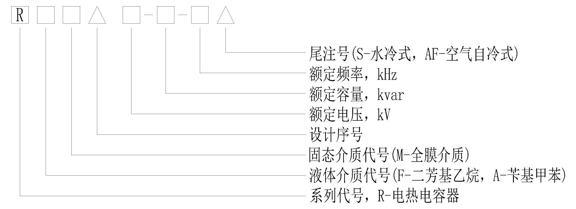

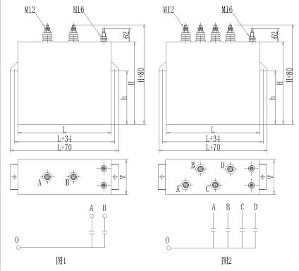
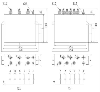
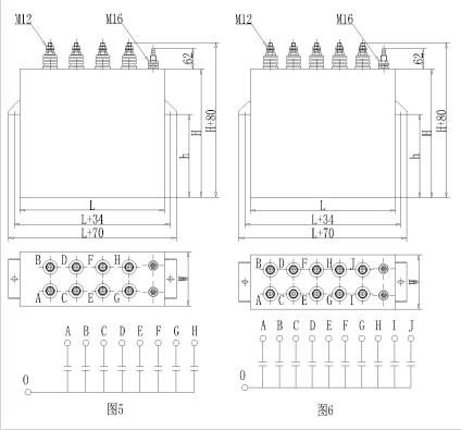
3. Product structure
3.1 The capacitor is mainly composed of shell, wiring guide bar and heart.
3.2 The shell is made of aluminum plate bent and welded, and it is equipped with capacitor heart, which is full of insulating oil with excellent electrical performance. The two ends of the shell are welded with brackets for installation and hoisting, and the shell cover is equipped with wiring guide rods sealed with silicone rubber and supported by porcelain bushing.
3.3 Capacitor core consists of several components, which are stacked into a whole through insulation gasket, splints, etc., in accordance with the design regulations. The cooling water pipe is directly welded into a whole with the component plate.
4. Conditions of use
4.1 The elevation of the installation site shall not exceed 1000m.
4.2 Indoor air temperature ranges from -40 ℃ to +45℃.
4.3 The remaining voltage at re-energizing shall not exceed 10% of the rated voltage.
4.4 Inlet pressure of cooling water shall not exceed 0.4Mpa, inlet water temperature shall not exceed 30℃, flow rate of cooling water shall not be less than 6L/min, cooling water shall be soft water without impurities, PH value shall be 6 ~ 9.
5. Main technical performance and data
5.1 Product Standards
Part I General for power capacitors for induction heating installations (equivalent to Part I general for power capacitors for induction heating installations IEC60110.1).
5.2 Capacitor terminals (electrode) can withstand 2.0UN power frequency test voltage for 10s.
5.3 For capacitors whose terminals are all insulated from the housing, the power frequency test voltage between the terminals and the housing shall be 2.15UN and at least 2000V for 10s.
5.4 Capacitance deviation range: no more than -5% ~ +10% of the rated value.
5.5 At rated power frequency voltage, the tangent value of capacitor loss Angle (tgδ) should not be greater than 0.0008
5.6 Overload: The capacitor can run continuously at rated voltage and 1.15 times rated current, and can run for no more than 12 hours every 24 hours at 1.05 times rated voltage.
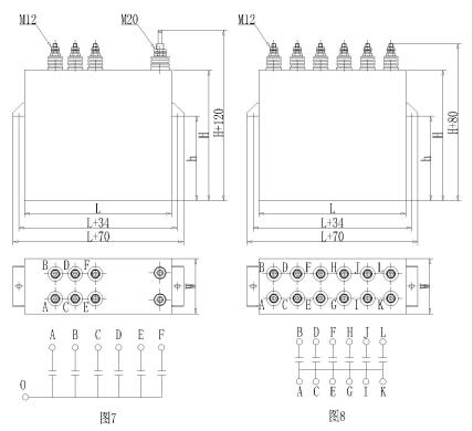
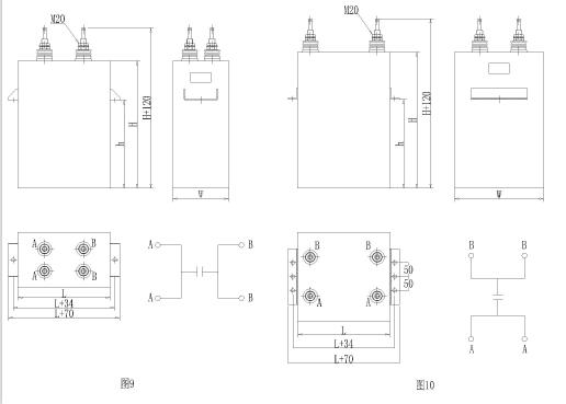
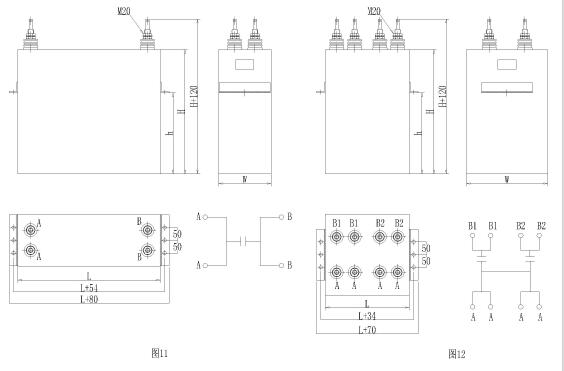
5.7 Main technical data and dimensions of capacitors (see attached table and attached figures 1-9).
The models, specifications, ratings and dimensions of capacitors are shown in the table
|
No. |
Capacitor model |
RATING |
Overall dimensions |
Weight(kg) |
Drawing No |
||||||||
|
UN (kV) |
QN (kvar) |
IN (A) |
CN |
fN (kHz) |
L |
W |
h |
H |
|||||
|
(uF) |
grouping |
||||||||||||
|
1 |
RFM0.375-500-1S |
0.375 |
500 |
1333 |
565.9 |
6 |
1.0 |
400 |
165 |
230 |
350 |
36 |
4 |
|
2 |
RFM0.375-500-2.5S |
0.375 |
500 |
1333 |
226.4 |
6 |
2.5 |
337 |
127 |
230 |
350 |
23 |
3 |
|
3 |
RFM0.75-360-1S |
0.75 |
360 |
480 |
101.9 |
2 |
1.0 |
337 |
127 |
180 |
270 |
18 |
1 |
|
4 |
RFM0.75-500-2.5S |
0.75 |
500 |
666.7 |
56.59 |
4 |
2.5 |
337 |
127 |
180 |
270 |
18 |
2 |
|
5 |
RFM0.75-560-4S |
0.75 |
560 |
746.7 |
39.61 |
4 |
4.0 |
337 |
127 |
180 |
270 |
18 |
2 |
|
6 |
RFM0.75-640-8S |
0.75 |
640 |
853.3 |
22.64 |
4 |
8.0 |
337 |
127 |
180 |
270 |
18 |
2 |
|
7 |
RFM0.75-1000-1S |
0.75 |
1000 |
1333 |
282.9 |
6 |
1.0 |
350 |
165 |
230 |
350 |
28 |
3 |
|
8 |
RFM20.75-1000-1S |
0.75 |
1000 |
1333 |
282.9 |
6 |
1.0 |
350 |
165 |
200 |
300 |
25 |
3 |
|
9 |
RFM0.75-2000-1S |
0.75 |
2000 |
2667 |
565.9 |
10 |
1.0 |
440 |
207 |
300 |
390 |
48 |
6 |
|
10 |
RFM0.9-2000-2S |
0.9 |
2000 |
2222 |
196.5 |
6 |
2.0 |
350 |
165 |
175 |
350 |
30 |
7 |
|
11 |
RFM0.9-2000-6S |
0.9 |
2000 |
2222 |
65.50 |
6 |
6.0 |
350 |
165 |
175 |
210 |
18 |
7 |
|
12 |
RFM0.9-2000-10S |
0.9 |
2000 |
2222 |
39.30 |
6 |
10.0 |
350 |
165 |
175 |
350 |
30 |
7 |
|
13 |
RFM1.0-1000-0.5S |
1.0 |
1000 |
1000 |
318.3 |
6 |
0.5 |
400 |
165 |
230 |
350 |
36 |
4 |
|
14 |
RFM1.0-1000-1S |
1.0 |
1000 |
1000 |
159.2 |
6 |
1.0 |
350 |
165 |
200 |
300 |
25 |
3 |
|
15 |
RFM1.0-2000-0.5S |
1.0 |
2000 |
2000 |
636.7 |
10 |
0.5 |
440 |
207 |
300 |
390 |
47 |
6 |
|
16 |
RFM1.2-1000-0.5S |
1.2 |
1000 |
833.3 |
221.0 |
6 |
0.5 |
400 |
165 |
230 |
350 |
36 |
4 |
|
17 |
RFM1.2-1000-1S |
1.2 |
1000 |
833.3 |
110.5 |
6 |
1.0 |
350 |
165 |
200 |
300 |
25 |
3 |
|
18 |
RFM1.2-1200-0.7S |
1.2 |
1200 |
1000 |
189.5 |
6 |
0.7 |
350 |
165 |
230 |
350 |
28 |
3 |
|
19 |
RFM1.2-2000-0.5S |
1.2 |
2000 |
1667 |
442.1 |
8 |
0.5 |
440 |
207 |
300 |
390 |
47 |
5 |
|
20 |
RFM1.2-2000-1S |
1.2 |
2000 |
1667 |
221.0 |
8 |
1.0 |
400 |
165 |
230 |
350 |
36 |
5 |
|
21 |
RFM1.4-1000-0.5S |
1.4 |
1000 |
714.3 |
162.4 |
6 |
0.5 |
400 |
165 |
230 |
350 |
36 |
4 |
|
22 |
RFM1.4-2000-0.5S |
1.4 |
2000 |
1429 |
324.8 |
8 |
0.5 |
440 |
207 |
300 |
390 |
47 |
5 |
|
23 |
RFM1.5-2000-1S |
1.5 |
2000 |
1333 |
141.5 |
6 |
1.0 |
355 |
165 |
325 |
500 |
43 |
7 |
|
24 |
RFM1.5-3000-0.5S |
1.5 |
3000 |
2000 |
424.4 |
1 |
0.5 |
355 |
200 |
490 |
745 |
65 |
9 |
|
25 |
RFM1.6-2000-0.5S |
1.6 |
2000 |
1250 |
248.7 |
6 |
0.5 |
390 |
207 |
300 |
430 |
46 |
3 |
|
26 |
RAM1.6-3778-0.35S |
1.6 |
3778 |
2361 |
671.1 |
1 |
0.35 |
330 |
320 |
475 |
800 |
110 |
9 |
|
27 |
RAM1.7-2260-0.5AF |
1.7 |
2000 |
1329 |
248.9 |
6 |
0.5 |
390 |
207 |
300 |
430 |
46 |
8 |
|
28 |
RAM1.7-3000-0.3AF |
1.7 |
3000 |
1765 |
550.7 |
6 |
0.3 |
390 |
207 |
540 |
680 |
72 |
8 |
|
29 |
RFM1.8-3000-1S |
1.8 |
3000 |
1667 |
147.4 |
8 |
1.0 |
390 |
165 |
300 |
430 |
36 |
5 |
|
30 |
RAM1.8-3787-0.3S |
1.8 |
3787 |
2104 |
620.1 |
1 |
0.3 |
330 |
320 |
475 |
800 |
110 |
9 |
|
31 |
RFM2.0-1500-0.5S |
2.0 |
1500 |
750 |
119.4 |
6 |
0.5 |
330 |
200 |
680 |
300 |
51 |
7 |
|
32 |
RFM2.0-2000-0.5S |
2.0 |
2000 |
1000 |
159.2 |
1 |
0.5 |
330 |
200 |
400 |
520 |
45 |
9 |
|
33 |
RFM2.0-2000-1S |
2.0 |
2000 |
1000 |
79.6 |
6 |
1.0 |
400 |
165 |
230 |
350 |
36 |
4 |
|
34 |
RFM32.5-2000-0.3S |
2.5 |
2000 |
800 |
169.8 |
1 |
0.3 |
330 |
200 |
600 |
760 |
64 |
9 |
|
35 |
RFM2.5-2000-0.3S |
2.5 |
2000 |
800 |
169.8 |
6 |
0.3 |
330 |
200 |
600 |
920 |
77 |
3 |
|
36 |
RFM2.5-2000-0.5S |
2.5 |
2000 |
800 |
101.9 |
1 |
0.5 |
330 |
200 |
440 |
570 |
48 |
9 |
|
37 |
RAM2.5-3000-0.3AF |
2.5 |
3000 |
1200 |
254.6 |
6 |
0.3 |
390 |
207 |
440 |
680 |
70 |
8 |
|
38 |
RFM2.5-4000-0.4S |
2.5 |
4000 |
1600 |
254.6 |
1 |
0.4 |
330 |
320 |
475 |
800 |
110 |
10 |
|
39 |
RFM32.9-2000-0.3S |
2.9 |
2000 |
689.6 |
126.2 |
1 |
0.3 |
330 |
200 |
600 |
760 |
63 |
9 |
|
40 |
RFM2.9-3000-0.3S |
2.9 |
3000 |
1034 |
189.2 |
1 |
0.3 |
330 |
200 |
600 |
920 |
80 |
9 |
|
41 |
RFM3.0-3000-0.5S |
3.0 |
3000 |
1000 |
106.1 |
6 |
0.5 |
330 |
200 |
100 |
780 |
64 |
7 |
|
42 |
RAM3.0-5400-0.3S |
3.0 |
5400 |
1800 |
318.3 |
1 |
0.3 |
560 |
207 |
570 |
820 |
116 |
11 |
|
43 |
RFM3.0-6000-0.5S |
3.0 |
6000 |
2000 |
212.2 |
1 |
0.5 |
330 |
290 |
100 |
78 |
91 |
10 |
|
44 |
RFM33.2-2000-0.3S |
3.2 |
2000 |
625 |
103.6 |
1 |
0.3 |
330 |
200 |
600 |
760 |
64 |
9 |
|
45 |
RFM3.2-3000-0.3S |
3.2 |
3000 |
937.5 |
155.4 |
1 |
0.3 |
330 |
200 |
600 |
920 |
80 |
9 |
|
46 |
RFM3.6-6000-0.5S |
3.6 |
6000 |
1667 |
254.6 |
1 |
0.5 |
330 |
320 |
475 |
800 |
110 |
10 |
|
47 |
RFM3.8-2000-0.2S |
3.8 |
2000 |
526.3 |
110.2 |
1 |
0.2 |
330 |
320 |
600 |
800 |
109 |
10 |
|
48 |
RFM3.8-3000-0.3S |
3.8 |
3000 |
789.5 |
110.2 |
1 |
0.3 |
330 |
200 |
600 |
920 |
80 |
9 |
|
49 |
RFM4.0-3000-0.4S |
4.0 |
3000 |
750 |
74.6 |
1 |
0.4 |
330 |
320 |
335 |
660 |
87 |
10 |
|
50 |
RFM4.0-3000-0.5S |
4.0 |
3000 |
750 |
59.7 |
1 |
0.5 |
330 |
320 |
235 |
560 |
75 |
10 |
|
51 |
RFM4.0-7500-0.4S |
4.0 |
7500 |
1875 |
186.5 |
2 |
0.4 |
390 |
330 |
515 |
840 |
138 |
12 |
Online consultation
Any questions can give us a message, we have professional staff to reply to you, please be sure to fill in the correct contact information!
Recommended products

Shangyu Power Capacitor is a manufacturing company specialized in reactive power compensation and improving the power factor of the power grid.
Contact us
Address:Chengnan Industrial Function Zone, Dongguan Street, Shangyu District, Shaoxing City
E-mail:drq@sy-capacitor.com
Copyright Shaoxing Shangyu Power Capacitor Co., Ltd. Powered by:www.300.cn business license
