


Automatic sitching eatve power compensation comple set
Environmental usage conditions:
a. The altitude of the area of use shall not exceed 1000m.
b. The ambient temperature in the area of use: -40~+45 ℃.
c. The place of use should be free from severe mechanical vibration, harmful gases and vapors, and conductive or explosive dust.
4.2 Other usage conditions:
Before the capacitor is put into operation, the remaining voltage between its terminals should not exceed 10% of the rated voltage. When capacitors involve high relative humidity, rapid mold growth, corrosive atmosphere, pollution, and altitude exceeding 1000m
Keywords:
Automatic sitching eatve power compensation comple set
Details
1 Overview
TBBZ automatic switching-type high voltage shunt capacitor set (hereinafter referred to as the "set") is our company's main product after the TBB high voltage shunt capacitor set. It is a static reactive power compensation device with dynamic regulation. Its performance conforms to the standards of GB/T 30841-2014 "General Technical Requirements for High Voltage Shunt Capacitor Devices" and GB50227-2017 "Design Specification for High Voltage Shunt Capacitor Devices".
The device groups capacitors according to capacity, selects appropriate automatic switching control device and special switching switch, continuously monitors the voltage and current signals of the system, calculates the reactive power demand in real time, and reasonably controls the switching of capacitor banks according to the set control strategy, so as to maximize the benefits of the capacitors. To meet the requirements of reactive power and voltage regulation.
2 Uses
It is mainly used for accurate reactive power compensation of 6kV, 10kV and 35kV power frequency power systems to maximize the power factor of the grid, reduce line losses and improve voltage quality.
3 Features
3.1 The device has simple structure, convenient installation, small investment and less maintenance.
3.2 Novel device design and various forms. Common forms available for users to choose include cabinet or steel frame structure for indoor use, and steel frame structure for outdoor use.
3.3 The device can be grouped according to equal volume and unequal volume, and multiple groups can be automatically switched and controlled accurately; Equal volume capacitor bank can be set cycle switching, prolong the service life of the device.
3.4 A variety of capacitor switching strategies are built into the device. Users can switch capacitors according to time period, voltage, reactive power, power factors and their combination strategies.
3.5 The device can add the function of adjusting the tap position of the on-load voltage regulating switch of the transformer as required, and reasonably control capacitor switching and transformer on-load voltage regulating switch based on comprehensive consideration of voltage fluctuation and reactive power deficit.
3.6 The device can display three-phase voltage, three-phase current, active power, reactive power, power factor, and main gear position in real time.
3.7 The device can provide capacitor overvoltage, undervoltage, open triangle voltage protection; Provide actuating switch (vacuum contactor) rejection protection. The device can monitor the harmonic THDv online and provide harmonic protection.
3.8 The device adopts Chinese LCD operating interface, provides RS232/RS485 communication interface, and can communicate with the substation central control system.
4 Technical Data
4.1 Main Parameters
4.1.1 Product Specifications
The total capacity of the device is recommended to be selected from the following values (kvar):
600, 900, 1200, 1500, 1800, 2100, 2400, 3000, 3300, 3600, 4200, 4500, 4800, 5100, 5400, 5700, 6000, 6600, 7200, 8400, 9000, 12000
The capacity of a single group is recommended to be selected from the following values (kvar) :
300, 600, 900, 1200, 1500, 1800, 2000
The number of device groups and capacity should be determined according to the system voltage fluctuation, load variation, background harmonic content of the grid and other factors. The resonant capacity should be avoided when the capacitors are operated in various capacity combinations.
Please contact us if you have any special needs.
4.1.2 Overall dimensions. The cabinet structure is arranged by component cabinet. The width of unit cabinet is 1200mm, the height is 2500 mm, and the depth is 1500mm. Each device is equipped with a wire cabinet. When the capacity of a group is not greater than 2000kvar, each group has one cabinet. When the capacity of a group is greater than 2000kvar, each group has two cabinets.
If the frame structure is used, it can be arranged according to the actual site, and the owner will provide the site plan.
The common wiring mode of the device is shown in Appendix A of the figure for user reference.
4.1.3 Rated frequency of device: 50Hz
4.1.4 Number of device phases: 3 phases
4.2 Main Performance
4.2.1 Loss Angle tangent value of capacitor in the device: full film medium structure, no more than 0.0005.
4.2.2 Capacitance deviation of the device: The deviation between the measured capacitance of the capacitor bank in the device and its rating shall not exceed 0 ~ +5%. The ratio between the maximum value and the minimum value of any two-phase measured capacitance of the capacitor bank is not greater than 1.02; The ratio between the maximum and minimum measured capacitance of each series segment is no more than 1.02.
4.2.3 The device is allowed to operate for a long time at 1.1 times the rated voltage.
4.2.4 The device is allowed to operate for a long time under steady overcurrent with an effective value of 1.3 times the rated current due to overvoltage and higher harmonics.
4.2.5 The back-to-back additional closing inrush current of the device shall not exceed 20 times the rated current of the capacitor bank (peak).
5 Structure
5.1 The device installed indoors is cabinet structure or section steel frame structure, and the device used outdoors is section steel frame structure.
5.2 Cabinet structure is generally composed of wire inlet cabinet and capacitor cabinet. The capacitor cabinet is equipped with switch, current transformer (as required), a single capacitor, reactor, arrester, discharge coil and other components. The cabinet body is made of high quality cold rolled steel plate and aluminum zinc steel plate, which is processed by advanced CNC machine tool. The surface is treated by pickling phosphating spray technology, and the cabinet body is beautiful.
5.3 JCZ vacuum contactor is generally used for switch switching of indoor devices, and vacuum load switch or circuit breaker is commonly used for outdoor devices to ensure safe and reliable frequent switching of capacitor banks.
5.4 The medium structure of the high-voltage shelled capacitors in the device is diarylethane impregnated polypropylene film or benzyltoluene impregnated polypropylene film. The rated capacity of a single capacitor is 100kvar, 200kvar, 334kvar, 500kvar, 667kvar, etc.
5.5 When the rated capacity of a single capacitor in the device is less than 200kvar, the external fuse is used as the first level of protection for internal faults; when the rated capacity of a single capacitor is more than 200kvar, the internal fuse is generally used as the first level of protection for internal faults.
The external fuse is connected with the capacitor in series. When there is a partial series breakdown inside a capacitor, the fuse will act to remove the faulty capacitor quickly and effectively prevent the expansion of the fault.
The internal fuse is connected in series with the internal components of a single capacitor. Once the component fails, the fuse is blown and the faulty component is removed, allowing the remaining parts of the single capacitor and the capacitor bank connected to the capacitor to continue to operate.
5.6 The discharge coil is connected in parallel in the capacitor loop. After the capacitor is removed from the grid, the remaining voltage on the capacitor can be reduced from √2Un to 50V or lower within 5s.
5.7 The zinc oxide arrester is connected in parallel to the wire to limit the operating overvoltage caused by switching capacitor banks.
5.8 Series reactors are connected in series in the capacitor loop, usually in the rear, to suppress the higher harmonics in the capacitor bank and limit the closing inrush current. When it is only used to limit inrush current, the reactance is selected from 0.1% to 1%. When it is used to suppress 5 or more high harmonics, the reactance rate is 5% ~ 6%. When it is used to suppress 3 or more high harmonics, the reactance rate is 12%.
6 Meanings of symbols in Models
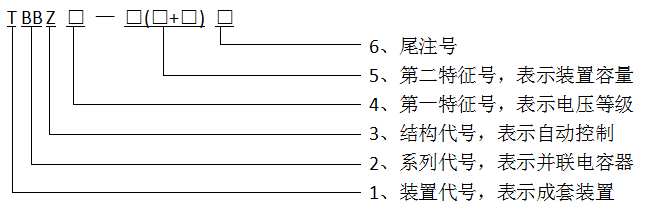
The model consists of 6 items:
1. Device code: Use capital Chinese pinyin letter "T" to represent "complete set of devices";
2, series code: with capital Chinese pinyin letter "BB" means "shunt capacitor";
3, structure code: with capital Chinese pinyin letter "Z" means "automatic control";
4, the first feature number: used to indicate the rated voltage of the device, the unit is kV. 6 and 10 are optional;
5, the second feature number: used to indicate the rated capacity of the device, unit kvar. Before the parentheses is the total capacity of the device, and inside the parentheses is the grouping capacity of the device. Group capacities are separated by + symbols. If the group capacities are the same, they are represented by capacity of one group x number of groups.
6, tail note number: with 2 ~ 3 each in capital Chinese pinyin letters. The first letter represents the main wiring mode of the device, and the meanings of the letters are shown in Table 2; The second letter represents the relay protection mode of capacitor banks. The meanings of the letters are shown in Table 3; The third letter indicates the application of the device, outdoors with a "W", indoor not marked.
The first letter of endnote number in Table 2 indicates
|
Letter |
meaning |
|
A |
single star |
|
B |
double star |
|
C |
three stars |
Table 3 Meaning of the second letter of endnote number
|
Letter |
meaning |
|
C |
Voltage differential protection |
|
K |
Open triangle voltage protection |
|
Q |
Bridge differential current protection |
|
L |
Neutral unbalanced current protection |
|
Y |
Neutral unbalanced current protection |
Example: TBBZ10 -- 3000(1200×2+600)AK, which means: Automatic switch type high voltage shunt capacitor complete set, voltage class is 10kV, the total capacity of the device 3000kvar, divided into 1200 kvar, 1200 kvar, 600 kvar three groups, single star connection, open triangle unbalanced voltage protection, suitable for indoor.
7 Conditions of Use
7.1 Installation and use place: indoor or outdoor.
7.2 The elevation of the installation and operation site shall not exceed 1000m.
7.3 Temperature Category: indoor -25/A Outdoor -40/A.
7.4 Relative humidity: daily average is not more than 95%, monthly average is not more than 90%.
7.5 There is no gas or steam that is seriously corrosive to metal, no electrical conductivity or explosive dust, and no violent mechanical vibration.
7.6 When the capacitor is put into operation, the remaining voltage on the terminal shall not exceed 10% of the rated voltage.
If you have other requirements, please contact us.
Appendix A Common wiring methods of the device
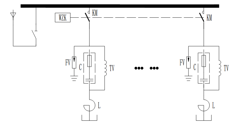
Single star connection, open triangle protection
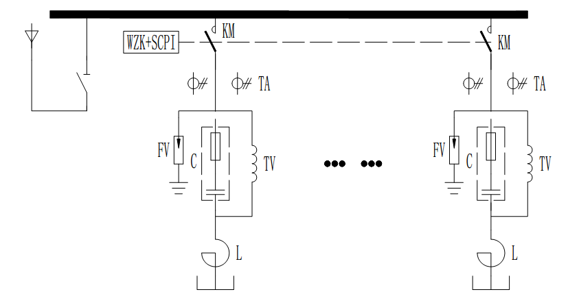
Single star connection, open triangle protection + single group overcurrent protection
Online consultation
Any questions can give us a message, we have professional staff to reply to you, please be sure to fill in the correct contact information!
Recommended products

Shangyu Power Capacitor is a manufacturing company specialized in reactive power compensation and improving the power factor of the power grid.
Contact us
Address:Chengnan Industrial Function Zone, Dongguan Street, Shangyu District, Shaoxing City
E-mail:drq@sy-capacitor.com
Copyright Shaoxing Shangyu Power Capacitor Co., Ltd. Powered by:www.300.cn business license
