


Low pressure column type reactive power compensation device
Environmental usage conditions:
a. The altitude of the area of use shall not exceed 1000m.
b. The ambient temperature in the area of use: -40~+45 ℃.
c. The place of use should be free from severe mechanical vibration, harmful gases and vapors, and conductive or explosive dust.
4.2 Other usage conditions:
Before the capacitor is put into operation, the remaining voltage between its terminals should not exceed 10% of the rated voltage. When capacitors involve high relative humidity, rapid mold growth, corrosive atmosphere, pollution, and altitude exceeding 1000m
Keywords:
Low pressure column type reactive power compensation device
Details
1. Overview
GWB0.4 series column type low-voltage reactive power compensation device is a new technology product developed by our company. It adopts high-quality self-healing low-voltage shunt capacitor, special switch for capacitor switching and advanced intelligent switching controller. It is packaged in stainless steel box and suitable for outdoor installation.
Main features:
1.1 Centralized collection and group compensation;
1.2 Optional three-phase cocomplement, phase separation compensation, or mixed compensation co-complement switching;
1.3 Compensation control technologies such as cycle switching and coding switching are adopted to ensure balanced use of each group, flexible capacity combination and low failure rate;
1.4 According to the principle of reactive power in situ balance, reactive power is taken as the direct control quantity;
1.5 Use special contactor for capacitor switching, or intelligent composite switch;
1.6 with perfect protection: overvoltage, undervoltage, overcurrent, lack of equal;
1.7 Optional communication function (GPRS).
2. Conditions of use
2.1 Ambient temperature: -25℃ to +55℃
2.2 The height of the sea dial shall not exceed 2000M
2.3 Relative humidity (at the ambient temperature of 40℃) : The air humidity does not exceed 90%
2.4 Atmospheric pressure: 79.5-106.0kPa
2.5 Environmental conditions: No conductive dust in the medium
2.6 Installation inclination: not more than 10 degrees
3. Technical specifications
3.1 Basic Technical Parameters
3.1.1 Rated input analog:
Rated input voltage simulation: 380V/AC±20%;
Rated input current analog: 0 ~ 5A/AC.
3.1.2 Measurement accuracy:
Voltage: 0.5 level
Current: Level 1.0
Power factor: Level 1.5
Reactive power: Level 2.0
Clock error: < 1 second/day
3.1.3 Control Physical quantity: reactive power Q
3.1.4 Controller Power consumption: ≤15VA
3.1.5 Number of Groups: 2 to 12 groups; When phase separation compensation is used, the last group is the phase separation compensation group.
3.1.6 Single-group capacity (three-phase) : 10 ~ 50kvar
3.1.7 Communication Mode: GPRS (Optional)
3.1.8 Control mode: manual and automatic
3.1.9 Switch: capacitor contactor, intelligent composite switch (optional);
3.1.10 Automatic Delay function
Capacitor switching delay: 10 ~ 120 seconds, can be set;
Group capacitor switching interval: ≥300 seconds.
3.1.11 Overvoltage/Undervoltage protection function
When the voltage is less than or equal to the set lower limit (0.65 ~ 0.93UN), the reactive power will not be invested, and all the invested power will be cut (sequentially cut).
When the voltage is higher than the upper limit (set in the range of 1.0 ~ 1.15UN), the reactive power is not invested, and the invested total cut (sequential cut);
3.1.12 Self-check and return function: After each power-on, the controller self-checks and returns the output loop to make it in open state.
3.1.13 Switch-off mode: automatic cycle switch-off, that is, the first switch-off is the first switch-off, and the later switch-off is the second switch-off, so that the capacitor banks work in turn;
3.1.14 Safety protection functions:
3.1.15 Short circuit protection: air circuit breaker protection;
3.1.16 Phase loss protection (three-phase sampling access) : When the line voltage is lower than 65% of the rated value, it will be regarded as phase break and the controller will cut out the output loop;
3.1.17 Insulation level: greater than 5MΩ under normal atmospheric conditions.
3.1.18 Data Storage Capacity: Refer to controller manual.
3.1.19 Data storage Days: Refer to the controller manual.
3.1.20 Switch History: Refer to the controller manual.
3.2 Technical Features
3.2.1 Control physical quantity: reactive power, no compensation idle area, small load does not produce switching oscillation.
3.2.2 Automatic phase sequence identification function: After the input B, C phase voltage and A phase current are connected correctly, the secondary terminals S1 and S2 of the CT can be connected arbitrarily without affecting the correct operation of the controller.
3.2.3 Encoding switching function: cyclic switching and encoding can be realized (when the capacity of each packet is different).
3.2.4 Multiple compensation methods: Group, phase or mixed compensation (optional).
3.3 Device structure
The box body of GWB0.4 series compensation device is made of stainless steel plate by bending and welding, and the top of the box body is provided with a rainproof sun cover. The box body is provided with a ventilation hole at the bottom, and the front and side of the box body are provided with a door that can be opened at least 90 degrees.
The dimensions of the device are shown in the figure below:
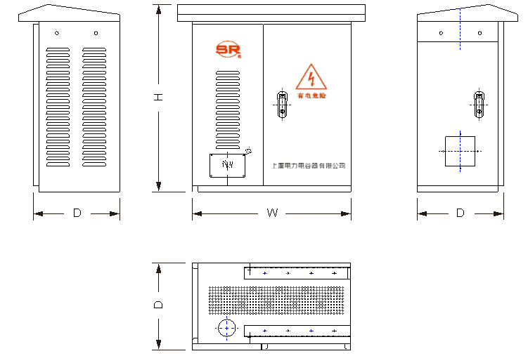
Figure 1. Dimensions of device appearance
Common configuration sizes: Unit: mm
| No. | Group Number | Width | Height | Depth |
|
1 |
2 |
400 |
650 |
300 |
|
2 |
3 |
475 |
650 |
300 |
|
3 |
4 |
550 |
650 |
300 |
|
4 |
6 |
700 |
650 |
300 |
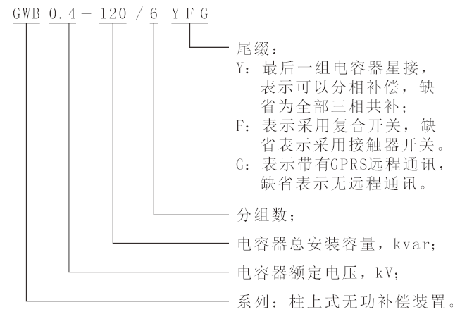
4. Name the model
4.1 Naming
4.2 Instructions for Ordering
The user should first calculate the reactive power capacity Qc according to the active power capacity P (kW) of the line (equipment) to be compensated, power factor with diameter of 1 before compensation, power factor with diameter of 2 after compensation, according to the following formula


Then select the number and capacity of the compensation group according to the actual load needs (the optimal value of the group capacity is 10, 15, 20, 25, 30, 40, 50kvar), and then give the specification number of the compensation device according to the naming rules of this series.
This is the theoretical calculation of the capacity, under normal circumstances according to the calculation value of the capacitor capacity can be selected. For accurate calculations, the rated voltage of the capacitor also needs to be taken into account. Because the rated capacity of the capacitor (i.e. the installed capacity) is the capacity under the rated voltage of the capacitor, and the capacity calculated by the above formula refers to the capacity of the compensating capacitor required under the actual running voltage of the line, and they are not equivalent. The relationship between them is as follows:

In the presence of a series reactor, the actual output capacity of the capacitor, minus the portion consumed by the reactor. When calculating the installed capacity, the capacity of the reactor should be added.
Online consultation
Any questions can give us a message, we have professional staff to reply to you, please be sure to fill in the correct contact information!
Recommended products

Shangyu Power Capacitor is a manufacturing company specialized in reactive power compensation and improving the power factor of the power grid.
Contact us
Address:Chengnan Industrial Function Zone, Dongguan Street, Shangyu District, Shaoxing City
E-mail:drq@sy-capacitor.com
Copyright Shaoxing Shangyu Power Capacitor Co., Ltd. Powered by:www.300.cn business license
