


High pressure column type reactive power compensation device
Environmental usage conditions:
a. The altitude of the area of use shall not exceed 1000m.
b. The ambient temperature in the area of use: -40~+45 ℃.
c. The place of use should be free from severe mechanical vibration, harmful gases and vapors, and conductive or explosive dust.
4.2 Other usage conditions:
Before the capacitor is put into operation, the remaining voltage between its terminals should not exceed 10% of the rated voltage. When capacitors involve high relative humidity, rapid mold growth, corrosive atmosphere, pollution, and altitude exceeding 1000m
Keywords:
High pressure column type reactive power compensation device
Details
1. Product use and characteristics
GWBJ column type automatic high voltage reactive power compensation device (hereinafter referred to as the device) is suitable for 10kV and 6kV distribution overhead lines, can provide reasonable reactive power compensation, reduce line loss, improve power factor, improve voltage quality; Can also be used for miniaturized terminal substation 10kV or 6kV reactive power compensation.
The device conforms to JB/T10558-2006 "Column type High voltage reactive power Compensation Device", DL/T604-1996 "High voltage parallel capacitor Device ordering Technical Conditions" and other standards.
The device can be based on the actual needs, the user can set the parameters, the controller in the device real-time monitoring of the reactive power and voltage state of the line, and according to the set reactive power and voltage control strategy to judge and analyze, realize the automatic switching of high voltage shunt capacitor bank. At the same time, the device has perfect protection functions, such as bus short circuit fast break protection, capacitor electrode short circuit delay protection, capacitor overcurrent short delay protection, overvoltage protection, undervoltage protection, phase loss protection (optional when ordering) and motion rejection protection, but also has the function of meter reading.
The vacuum contactor used in this device fully meets the requirements of GB7675-87 for capacitor switching, with good contact closing characteristics, strong arc elimination ability, long life and so on. High voltage shunt capacitor with internal discharge resistance, equipped with external drop fuse, safe and reliable. Select user - shaped high voltage capacitor automatic controller, strong anti-interference ability, complete functions, good quality.
The device is an exterior integrated box structure, easy to install and easy to maintain.
2 Usage Conditions
2.1 Altitude: no higher than 1000m;
2.2 Wind speed: no more than 35m/s;
2.3 Earthquake: seismic intensity does not exceed 8 degrees;
2.4 Sunshine: the maximum amplitude is 0.1w/cm2;
2.5 Ambient air temperature: upper limit +45℃, lower limit -40℃;
2.6 Installation site: no harmful gas and vapor, no electrical conductivity or explosive dust;
2.7 Installation inclination shall not exceed 5 degrees.
3 Model Meaning and product specifications
3.1 Model Definition:
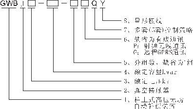
Example: GWBJ10-200-PQY: column type high voltage reactive power compensation device, 10kV voltage class, rated capacity of 200kvar capacitor 1 group, radio frequency mode communication, 5 groups of control strategy, capacitor star connection.
3.2 Product specifications and main technical data
|
No. |
Model |
Rated voltage kV |
The rated voltage of the capacitor bank is kV |
Rated capacity kvar |
Rated current A |
Capacitance deviation |
Allow steady-state overvoltage |
Allow steady state overcurrent |
Shunt capacitor type |
Capacitor quantity |
|
1 |
GWBJ10-100 |
10 |
11 |
100 |
5.2 |
0~10% |
1.1 the Un |
1.3In |
B |
1 |
|
2 |
GWBJ10-200 |
10 |
11 |
200 |
10.5 |
B |
1 |
|||
|
3 |
GWBJ10-300 |
10 |
11 |
300 |
15.7 |
B |
1 |
|||
|
4 |
GWBJ10-600 |
10 |
11 |
600 |
31.5 |
B |
2 |
|||
|
5 |
GWBJ10-900 |
10 |
11 |
900 |
47.2 |
B |
3 |
|||
|
6 |
GWBJ6-100 |
6 |
6.6 |
100 |
8.7 |
B |
1 |
|||
|
7 |
GWBJ6-200 |
6 |
6.6 |
200 |
17.5 |
B |
1 |
|||
|
8 |
GWBJ6-300 |
6 |
6.6 |
300 |
26.4 |
B |
1 |
|||
|
9 |
GWBJ6-600 |
6 |
6.6 |
600 |
52.5 |
B |
2 |
|||
|
10 |
GWBJ6-900 |
6 |
6.6 |
900 |
78.7 |
B |
3 |
 M11-100-3W
Note: Only some models are listed in the table. In actual selection, you can combine them freely according to the items in the model definition.
4. Structure and working principle
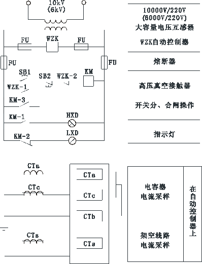
4.1 The device is composed of drop fuse, zinc oxide arrester, voltage mutual inductor type power transformer, special high voltage vacuum contactor for capacitor switching, current transformer, high voltage shunt capacitor, outdoor high voltage capacitor automatic control device and box, etc. 4.2 Schematic Diagram 1 is the electrical schematic diagram of a single group of capacitors for reference. For details, please refer to the product documentation. WZK is an automatic controller. By continuously measuring the voltage (TVB) of UV phase and the system current (TA1) of W phase, the voltage level, power factor and reactive power demand of the system are obtained. According to the set control strategy, the KM vacuum contactor is used to control the input and removal of capacitors.
Figure 1 Electrical schematic diagram (single group reference)

|
TVB |
Large capacity voltage transformer |
FV1 |
Distribution type zinc oxide arrester |
|
WZK |
Outdoor high voltage capacitor device automatic controller |
FV2 |
Capacitive zinc oxide arrester |
|
KM |
Ac high pressure vacuum contactor |
DR |
Drop type fuse |
|
TA1 |
Outdoor open type high voltage current transformer |
C |
High voltage shunt capacitor |
|
TA2 |
Bushing current transformer |
FU |
Low pressure control protects fuses |
4.3 Secondary Cable Connections
FIG. 2 is the secondary wiring diagram of single capacitor specifications for your reference. For details, please refer to the data attached with the product.
SB1 and SB2 are manually operated buttons, and WZK-1 and WZK-2 are throw and cut control contacts provided by WZK. When SB1 or WZK-1 is closed, KM draws and the capacitor is put in; When SB2 or WZK-2 is disconnected, KM is released and the capacitor is removed. CTa and CTc collect capacitor current, monitor capacitor input and detect capacitor failure.
The HXD is the input indicator and the LXD is the removal indicator, which is located in the lower part of the device for easy observation by the ground personnel.
Figure 2 Secondary connection (single group reference)
4.4 Main electrical equipment
4.4.1 Capacitor
This device uses BFM or BAM full film high voltage shunt capacitors with built-in discharge resistance.
Note: Although the capacitor charge has been discharged to less than 50V through the discharge resistance 5 minutes after the capacitor is out of operation, it is still not allowed to touch the capacitor by hand. Instead, the grounding rod with an insulated handle should be used to short-circuit the two terminals of the capacitor for discharge, and the terminals can be reliably grounded before touching the capacitor.
See the capacitor instruction manual for details.
4.4.2 Indoor AC high-pressure vacuum contactor
Ac high-voltage vacuum contact is a new generation of capacitor switching equipment, its technical indicators meet the requirements of the national standard GB7675-87 "AC high-voltage vacuum circuit breaker on and off capacitor bank test", and long life, in rated current up to 200,000 times. This is important for frequent switching when reactive power compensation is used.
See the vacuum contactor instruction manual for details.
Sulfur hexafluoride load switch or column vacuum switch can also be used if user needs.
4.4.3 Automatic control device for outdoor high-voltage capacitor
WZK outdoor high voltage capacitor automatic controller, using microcomputer technology, through real-time sampling system voltage and system current, according to the time, voltage, power factor and their combination and other strategies automatically switch capacitor, switching range can be set by the user according to the actual line situation, in order to achieve the best compensation effect. At the same time, the automatic controller is equipped with overvoltage protection, undervoltage protection, overcurrent protection and delay function, and its setting value can be set according to the need. When the capacitor internal fault occurs after the over-current trip, the automatic control will lock itself. The controller can record events and has a communication interface to communicate with external intelligent devices through wired or wireless means.
For details, see the controller manual that comes with the product.
4.4.4 Zinc oxide Arrester
HY5WS zinc oxide arrester is used for lightning overvoltage protection. It is used to protect and control power transformers and vacuum contactors. HY5WR type zinc oxide arrester is used for capacitor protection and overvoltage protection.
The main technical parameters are shown in the following table:
Main technical parameters of zinc oxide arrester
| Model |
Rated voltage of arrester (kV) |
System rated voltage (kV) |
Continuous operating voltage (kV) |
Peak DC 1mA reference voltage (kV) |
Peak residual voltage of lightning impulse current (kV) |
Peak residual voltage of operating impulse current (kV) |
2ms square wave flow capacity (A) |
|
HY5WS-10/30 |
10 |
6 |
8.0 |
15.0 |
30 |
25.5 |
75 |
|
HY5WS-17/50 |
17 |
10 |
13.6 |
26 |
50 |
42.5 |
75 |
|
HY5WR-10/27 |
10 |
6 |
8.0 |
13.8 |
27 |
20.8 |
400 |
|
HY5WR-17/45 |
17 |
10 |
13.6 |
24 |
45 |
38.3 |
400 |
4.4.5 Voltage mutual inductor transformer
The component provides low-voltage operating power supply, and also acts as a voltage transformer to provide line voltage sampling. The ratio is 10/0.22kV or 6/0.22kV, and the accuracy is level 1.
4.4.6 Drop type fuse
RW10-10F drop type fuse, creepage specific distance ≥25mm/KV, rated breaking capacity of 100MVA. The fuse adopts the new "T" type melt promoted by the Ministry of National Resources, which has excellent fusing characteristics. The rated current of the fuse should not be less than 1.5 times the rated current of the device, but should not be larger than the following requirements: Check the amperity-per-second characteristic curve of the fuse based on the maximum short-circuit current at the installation site. The fusing time should be less than 0.15 seconds.
4.4.7 Current Transformer (for power factor sampling)
LZKW-10 type current transformer factory power frequency voltage resistance is 35kV, 1 minute through (American national standard), the transformer structure is reasonable, high measurement accuracy. Easy to install and long service life.
Figure 3 Enclosure dimensions
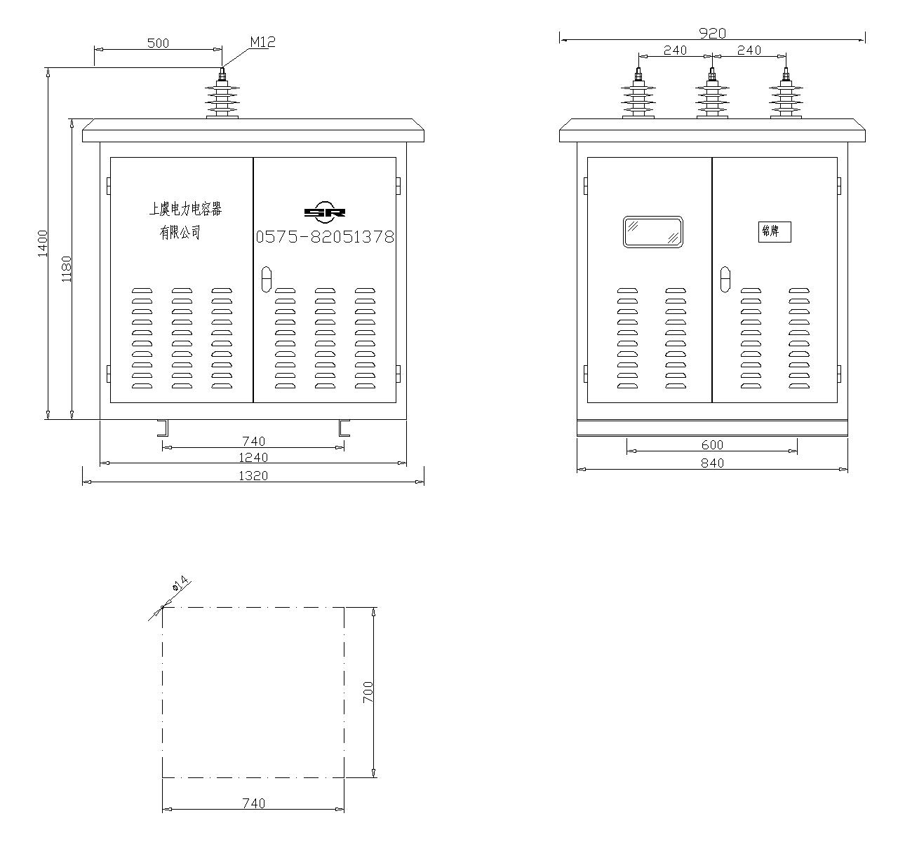
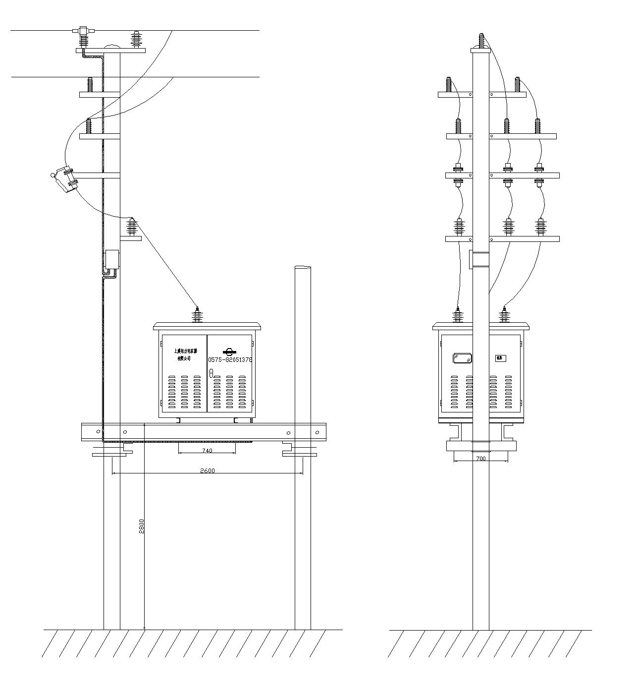
Figure 3 External connection diagram
Online consultation
Any questions can give us a message, we have professional staff to reply to you, please be sure to fill in the correct contact information!
Recommended products

Shangyu Power Capacitor is a manufacturing company specialized in reactive power compensation and improving the power factor of the power grid.
Contact us
Address:Chengnan Industrial Function Zone, Dongguan Street, Shangyu District, Shaoxing City
E-mail:drq@sy-capacitor.com
Copyright Shaoxing Shangyu Power Capacitor Co., Ltd. Powered by:www.300.cn business license
